Warpage Prediction

At the point when the embellishment comprises of a solitary shut zone, the material inside the trim is in constant contact with the end goal that any nonuniform shrinkage and stresses over the part may just be settled all through of plane twisting of the part. Injection mould manufacturers in china know that such warpage requires clasping of the plane of the part, which can happen when: (S edge一 S center)> 0.44. (h/W) (h/W)

where h is the divider thickness of the trim, and Scenter and Sedge are the shrinkage rates at the middle and edge of the part, and W is the good ways from the middle to the edge of the embellishment. This clasping examination models the embellishment as an isotropic roundabout plate under uniform outspread edge pressure with a clasping pressure limit of.

As the past warpage investigations have appeared, warpage is brought about by nonuniform shrinkage because of temperature inclinations through the divider thickness of the formed part, pressure angles over the territory of the shaped part, or temperature slopes aCross the zone of the shaped part. These are the most widely recognized reasons for warpage, and have been treated by high-precision mould china with the least complex conceivable examination. In any case, there are different reasons for nonuniform shrinkage including direction and remaining pressure. For additional data, the intrigued form fashioner is alluded to the examination writing.

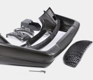
Sensibly exact warpage forecasts may likewise be gotten with PC recreation as recently talked about. oem/odm largest plastic injection molding companies gives the warpage forecast from PC recreation for the reproduction portrayed for Fig. 10.8. The outcomes recommend that the center of the part will bow down while the left and right sides of the bezel will bow upwards. The purpose behind this conduct is the upper surface of the bezel contains more material, and this upper surface is contracting not exactly the lower part of the ribs.

Given that warpage can be huge contrasted with shrinkage, shape fashioners may decide to make up for warpage by invert biasing the form surfaces dependent on anticipated or noticed warpage. This predisposition is some of the time alluded to as “Kentucky windage,” a shooting term that alludes to the changes a separation shooter must make to represent the breeze [26]. In this manner, Kentucky windage in form configuration alludes to the shaping of the form cavity surfaces with the end goal that after twisting the formed part smoothes to the ideal shape. The utilization of such predisposition isn’t without discussion, since it acquires cost in the forming of shape cavity surfaces while likewise intrinsically changing the warpage and auxiliary conduct of the formed parts. Therefore, it stays a to some degree uncommon practice in oem/odm medical injection mold factory.

Break down warpage accepting that the cup top is focus gated and shaped with ABS at a pressing weight of 66 MPa at the focal point of the part and 0 MPa at the external edge. To assess the warpage, it is first important to compute the shrinkage rates and check the clasping basis. Given the 66 MPa pressing weight and a temperature of 132°C, the straight shrinkage at the middle will be 0.3 1% at the middle. At the edge, the weight of 0 MPa and temperature of 132°C gives a direct shrinkage of 1.66 %. Given that the cup is 2 mm in thickness and 81 mm in breadth, the clasping measure is expressed.

This article is from https://www.injectionmouldchina.com

Final Shrinkage

The disastrous the truth is that to china mould manufacturing manufacturers, the specific shrinkage won’t be known before the shape is planned, manufactured, and tried. The objective in the setting up the last shrinkage proposal

■to give a shrinkage esteem that is near the real shrinkage of the material,

■to furnish a form machined with a shrinkage esteem that might be worked under a scope of cycle conditions to bring the part measurements inside particular, and

■to give a form that is machined”steel safe” with the end goal that the shape can be promptly adjusted if important to bring the part inside determinations.

The introduced shrinkage investigation should give sensible shrinkage gauges given legitimate dissolve temperatures and soften pressures. In any case of plastic injection moulded components china, the assessed contract age can differ broadly given vulnerability about material properties and handling conditions. Therefore, the shrinkage investigation ought to be considered as supplementing different wellsprings of data about shrinkage, The shrinkage examination ought not be utilized in disconnection given the potential for blunder. Notwithstanding, the shrinkage examination ought to be utilized to confirm the shrinkage gauges coming from different sources.

There are a few normal wellsprings of shrinkage information that might be utilized (notwithstanding examination) to help  plastic injection mold manufacturers china with setting up the last shrinkage proposal. Most ordinarily, a material provider or other testing research center may shape parts in a standard test form to assess the shrinkage. Commonly, the test form comprises of a 2 or 3 mm thick plaque that is shaped at mid-range dissolve temperatures and weights. The formed parts are then permitted to equilibrate for quite a while before their measurements are estimated and the straight shrinkage determined. This shrinkage data, when accessible, is generally precise since the testing was led for the specific material of interest at conditions near most embellishment applications. In any case, the gave shrinkage information may not be exact if the divider thickness or handling states of the embellishment application differ essentially from that of the test shape.

One critical issue with shrinkage information from a material provider is that the shrinkage information may not be founded on testing of the genuine material by high-precision molds made in china, but instead suppositions that the material will carry on as evidently comparative materials that have been recently tried. A more costly however more precise option is to configuration, assemble, and test a model shape that has a stream length, divider thickness, and cooling framework like the particular embellishment application. Such model embellishment gives dissolve weights and temperatures that ought to be fundamentally the same as those of the last creation form, so the shrinkage saw with the model shape should be near the last production form. While the advancement of a model shape can be costly, the exactness of the shrinkage estimations can be helpful in close resilience applications.

Another choice is to depend on shrinkage information from past form plans and decay insight. Much of the time, molds may as of now have been planned and worked for creation of moldings that are fundamentally the same as the current form plan application. In such cases, the mold originator of injection molding service china may acquire the best gauges by contrasting the estimations of the moldings and those of the shape steel measurements.

Before making last proposals, in any case, the shape originator ought to ask with the decay to check if the disintegrate would have liked to work the trim machine at various liquefy temperatures as well as weights. Provided that this is true, the form originator ought to ask the disintegrate to create moldings at the favored conditions (regardless of whether the moldings fall outside of determination), and afterward ascertain the shrinkage of these moldings for use in shape plan applications.

A fourth choice is to perform modern PC reenactment of the mold filling, pressing, and cooling stages to foresee the straight shrinkage in the trim application. While PC reproduction uses further developed material science and gives more definite outcomes than the shrinkage examination introduced here, the PC reenactment is as yet dependent upon similar mistakes with respect to the expected material conduct and preparing conditions. Nonetheless, the mathematical recreation can be important to approve the manual shrinkage examination while giving nonuniform shrinkage gauges over the shape pit.

In building up the last shrinkage suggestion, the form architect ought to play out the introduced shrinkage investigation and affirm the outcomes with information from the material provider and past experience, if accessible. On the off chance that the shrinkage rate is dubious, at that point the shape fashioner ought to discuss the expected blunder with the disintegrate, material provider, and end-client to diminish the vulnerability and survey obligation should the used shrinkage rates be so incorrect to bring about expensive form changes. In certain agreements, the last shrinkage proposal is the duty of the form’s client who eventually pays for the expense of the shape plan and any slip-ups. In different cases, no gathering might be happy to acknowledge duty regarding a questionable shrinkage rate, so the gatherings may concur that a model embellishment venture is important to portray the shrinkage and diminish hazard.

This article is from https://www.injectionmouldchina.com

Shrinkage Prediction

PC reenactment is an undeniably basic in plastics item and form plan for china injection molded parts factory, with Autodesk/Moldflow, Core Iech/Moldex3D, and Sigma Engineering/Sigmasoft giving shrinkage assessment to shaped parts. To exhibit the examination for the bezel, Autodesk/Moldlow (Molding Plastics Insight, MPI 2014 [8]) was performed for Cycolac MG47. The isotropic shrinkage rates anticipated by the recreation are given in injection mold services china expecting similar conditions as the earlier investigation: a mid-range liquefy temperature, mid-range coolant temperature, a steady pressing weight of 66 MPa for a period of6 s, and a cooling season of 20 s.

The outcomes demonstrate that the shrinkage changes generally over the form hole. Low shrinkage rates (on the request for 0.3 % and underneath) are anticipated in the slight territories around the edge that freeze at high dissolve pressures. Specifically, the most minimal shrinkage of 0.1 % adjoining the door is anticipated as this region of the hole totally freezes at high soften pressures over 100 MPa while the polymer liquefy is filling the rest of the pit. Moderate shrinkage rates (around 0.6%) are anticipated in the majority of the part, which is more than the 0.31 % shrinkage recently anticipated by the manual investigation. High shrinkage rates (over 1 %) are anticipated close to the furthest limit of fill. The high shrinkage rate toward the finish of fill is because of the way that the material closer the entryway is hardening and forestalling extra polymer liquefy from arriving at the finish of stream to make up for volumetric shrinkage.

The outcomes show a critical issue for the shape planner and the end-client: what shrinkage worth ought to be utilized? In the event that a normal shrinkage of 0.6% is utilized, at that point the part width might be out of detail due to the exorbitant unaccounted shrinkage along the top and base edges.

There are a few unique procedures that can be utilized by the shape planner if nonuniform shrinkage happens. One progressively regular technique, which is upheld by the joint utilization of PC reproduction and CNC machining, is for the form planner to utilize distinctive shrinkage esteems in various parts of the shape. For the PC bezel appeared in oem/odm injection mould factory, the decay may pick a shrinkage estimation of 0.7% for the left and right sides and a shrinkage esteem over 1 % for the top and base sides. In this model, this procedure is moderately simple to utilize and would probably be fruitful since the calculation is generally straightforward. For more unpredictable item calculation with a firmly interconnected surface, in any case, the utilization of non-uniform shrinkage esteems can turn into an intricate and hazardous undertaking.

Another regular way to deal with acquiring tight resistances is to guarantee more uniform shrinkage over the form hole through the expansion of various entryways. By expanding the quantity of entryways for the PC bezel from two to four as appeared in china plastic injection molding, the filling and pressing weights and in this way the shrinkage rate are completely made more uniform over the form pit. In this model, the extra two entryways have diminished the greatest shrinkage from 1.3 % at the focal point of the top edge in Fig. 10.8 to 0.74% at the corners in high precision plastic injection mould factory. Besides, the normal shrinkage in the hole has been decreased from 0.7 % for the twogated shape plan to 0.65% for the four-gated form plan.

Processing

Since the specific shrinkage rate is obscure, a typical practice for shape creators is to plan and assemble the form so it is”steel safe.” In this context,”steel safe” implies that the center and pit embeds are intentionally planned so they can be developed by eliminating existing mold metal if the product measurements are discovered to be modest. For instance, the normal shrinkage rate in an embellishment application might be 0.5%. A”steel safe” plan may use a shrinkage pace of 0.4% on the depression embed, and a 0.6 % shrinkage rate on the center supplement. Such a form plan procedure is appeared in plastic precision injection mould manufacturers china. By planning the depression more modest and the center bigger than needed by the normal shrinkage conduct, the form originator is giving store metal that may promptly be machined to calibrate the components of the shape.

One downside to a”steel safe”mold configuration is that machining will be fundamental in some trim applications paying little mind to the shrinkage conduct that is experienced. The explanation is that by using diverse shrinkage gauges for the center and depression, the ostensible elements of the plastic moldings will be out of resistance. Thus, many shape architects from china injection molded parts factory like to utilize a consistent however mid-range gauge of the shrinkage for the plan of the center and depression embeds, and trust that the decay can change the embellishment cycle to meet quality determinations. Another common”steel safe” practice is to try not to complete basic pit subtleties until after the form is built and tried. By leaving highlights, for example, supervisors, snap fits, and other form pit surfaces in a semi-completed express, the shape originator can finish the plan and execution of these highlights after the shrinkage has been portrayed. While such organized arrangement of highlights in the form configuration stretches the shape fabricate time, the danger during mold advancement is diminished and the resilience of the last moldings can be expanded.

As the investigation has appeared, the volumetric and straight shrinkage are needy upon the soften temperature and weight. Accordingly, disintegrates often depend on change of the embellishment conditions to control the shrinkage and streamline the part measurements [12]. The impact of a few basic preparing conditions on shrinkage is appeared in china standard components for injection mold and are predictable with the noticed shrinkage conduct gave in Table 10.1. The essential factors, true to form, are identified with the weight and temperature of the liquefy in the cavity. Both pressing time and cooling time are critical however small affect shrinkage when adequate pressing and cooling times are utilized by pom moulding products made in china. The coolant temperature has a somewhat more noteworthy impact than Adjustment of the trim cycle gives critical opportunity to alter the ostensible shrinkage rate in the form cavity. To impact the circulation of the shrinkage as a component of position in the form pit, it is conceivable to profile the pressing strain to control the dissolve pressure in the cavity as the soften sets at various areas and times. In particular, a higher pressing weight might be at first utilized toward the beginning of pressing to decrease the shrinkage rate at separations a long way from the door. The pressing weight may then be diminished as the material closer to the door freezes to abstain from over-pressing. To show this methodology, a pressing weight profile was utilized in the mathematical reenactment with the two-gated shape plan.

This article is from https://www.injectionmouldchina.com

Shrinkage Analysis

As a rule, for high precision plastic injection mould suppliers, inadmissible nonuniform shrinkage isn’t perceived until after the shape is planned, manufactured, and tried. At times, the expansion of sprinters and entryways might be a moderately basic and cheap action. In different cases, nonetheless, the expansion of two doors may end up being costly, with negative repercussions on weave line areas and feel. For instance, the alteration from a two-drop “straight bar”” complex to a four-drop “H”or”X” style complex may require the buying of another complex, the expansion of bores to the A-side of the form, and the re-directing of cooling lines. By and large, the form planner and disintegrate will initially attempt to address the shrinkage conduct through preparing or material changes as portrayed in  oem/odm automotives mold factory.

For approval of the portrayed shrinkage examination, economically accessible soften temperature and weight sensors were stacked to supplant ejector pins in a form for creation of 3.2 mm thick, ASTM pliable bars [9]. As appeared in OEM/odm medical injection moulding design factory, every infrared dissolve temperature sensor (Futaba EPSSZL) supplanted an ejector pin that heaps a soften pressure sensor (Futaba SSB1KN) situated inside the ejector retainer plate. The weight applied by the polymer liquefy to the uncovered surface of the temperature sensor gave a push power to the dissolve pressure sensor.

A Design of Experiments (DOE) was executed as appeared in Table 10.1 for trim the test examples of polypropylene. The 18-run configuration is full factorial as for 3 degrees of pack weight and 3 degrees of slam speed. The form coolant and barrel temperatures were hindered to rehash the full factorial plan at low and significant levels of temperature.

Figure 10.11 plots the obtained soften temperature signal close to the entryway for the primary pattern of every one of the DOE runs; the striking follow relates to run 14. The temperature signal starts close to the form coolant temperature. As the polymer liquefy passes the sensor, the temperature moves to a level close to the barrel temperature. The detected dissolve temperature fluctuates with the barrel temperature and infusion speed settings. There is an outstanding rot in the detected soften temperature as the warmth is directed to the cooler shape as per the investigation of Eq, 9.4. There is a later deferral in the cooling somewhere in the range of 20 and 25 s, likely because of inert warmth of combination as the polymer sets.

Figure 10.12 plots the depression pressure close to the door for similar cycles plotted in china precision plastic injection die manufacturers. The nature of the signs is incredible considering the utilization of the temperature sensor as a heap transmission medium. The impact of the three pack pressure settings is obviously noticed comparing to top depression pressures around 25, 50, and 75 MPa. A slight counterbalance in the hour of the pinnacle soften pressure is seen which compares to the adjustments in the infusion speed. The barrel and coolant temperature settings influence the pinnacle pit pressure just as pace of rot during pressing.

The particular volume of the polymer is plotted in high precision plastic injection mould manufacturers for run 14 of the DOE utilizing the weight volume temperature (PvT) shrinkage model of china industrial injection moulding manufacturers. During the embellishment cycle, the warmed polymer changes from semicrystalline strong to shapeless liquid around 170°C. During flling and pressing, expanded weight packs the dissolve thus lessens the particular volume. The particular volume at that point diminishes as the polymer in the pit encounters further pressing/cooling.

This article is from https://www.injectionmouldchina.com

Volumetric Shrinkage

As the polymer melt fills, packs, and cools in the form hole, it will be exposed to a scope of liquefy weights and temperatures. Simultaneously, the particular volume of the polymer melt in the cavity will change as needs be. oem/odm 2 shot injection moulding factory gives the melt’s weight, temperature, and explicit volume history during a trim cycle.

china mould design services demonstrates that during plastication, the soften’s temperature and explicit volume increments. During filling, the soften temperature is almost consistent, however an expanded liquefy pressure causes a decrease in the particular volume. During pressing, the material cools with a decrease in weight and temperature, causing a further decrease in the particular volume. After the finish of the pressing stage, no extra material is constrained into the form hole, The melt cools and therapists, causing the soften strain to rot. When the soften pressure arrives at air pressure, the plastic can pull away from the shape divider, with additional volumetric shrinkage making malleable burdens create in the formed part. Toward the finish of the cooling stage, the form opens and any lingering melt pressure is delivered. The part is then shot out and permitted to cool to room temperature.

The particular volume of the plastic after every one of the different embellishment stages is spoken to by china mould manufacturing manufacturers with a scale multiple times the qualities diagramed in plastic injection mold manufacturers china. Each solid shape contains the soften temperature and weight toward the finish of various trim stages, while the size of each 3D square speaks to the particular volume of the melt.

Plastic prototype mould china show that the particular volume subsequent to cooling is 0.97, and the particular volume after launch (when the part has cooled to room temperature) is 0.955. In that capacity, the adjustment in the particular volume of the plastic is – 0.015. This adjustment in the particular volume will lead legitimately to straight shrinkage in the components of the shaped plastic part. The assessment of the volumetric shrinkage toward the finish of the pressing stage is significant to the computation of the volumetric and direct shrinkage.

A sensibly precise gauge of the volumetric shrinkage can be determined if the melt weight and temperature toward the finish of the pressing stage are known. As recently talked about, the soften pressure in the cavity during pressing was assessed as 66 MPa. The temperature of the plastic in the depression is a component of the material properties, form calculation, and handling conditions. In the event that the pressing time is known, at that point the normal liquefy temperature can be assessed as talked about in Chapter 9. Notwithstanding, a more basic methodology is to expect that the soften temperature toward the finish of the pressing stage is equivalent to the no-stream liquefy temperature, which is the temperature at which the polymer has a high consistency. The no-stream temperatures for an assortment of materials are given in Appendix A.

The adjustment in the particular volume can be determined as the adjustment in the particular volume of the plastic toward the finish of the pressing stage and the particular volume of the plastic during end utilization of the shaped part.

Since the no-stream temperature of 405 K is over the change temperature of 386 K,the coefficients for the soften state ought to be utilized. The particular volume toward the finish of the pressing stage (66 MPa and 405 K) can be determined.

This article is from https://www.injectionmouldchina.com

Shrinkage

Plastic part originators regularly use plan for assembling and get together (DFMA) rules to lessen the quantity of parts in a gathering for injection mold manufacturing china. Hence, plastic part plans can be incredibly perplexing with numerous highlights and tight resistances.

The conveyance of plastic moldings that fulfill the dimensional prerequisites is a joint duty of the form architect, disintegrate, material provider, and part planner. The part planner ought to furnish a plan with uniform thicknesses and reachable determinations. The material provider ought to give steady polymer tar and helpful direction with respect to material properties. The disintegrate should choose reasonable and reliable handling conditions for activity of the shape. The form planner ought to furnish a shape with adjusted liquefy filling and cooling, and for which the form cavity measurements were designed for a suitable shrinkage.

The shrinkage of shaped plastic parts is administered essentially by the warm withdrawal of the plastic, the compressibility of the plastic at pressing weights, and less significantly by the warm development of the form metal. The grouping of steps that decides the last part measurements is appeared in double coler mold parts manufacturers. Preceding embellishment, the form cavity measurements may change somewhat from the machined measurements given that the shape might be at a coolant temperature over the room temperature. The warm extension of the shape cavity, shown by the ran lines in mold manufacturer factory, can be assessed as the shape metal’s coefficient of warm extension increased by the temperature contrast between the form coolant and room temperature. For a P20 form embed, the coefficient of warm extension is 12.8. 10-6 m/m°C. In the case of embellishment ABS, the shape working temperatures may be 60°C, which is 40°C above room temperature. In that capacity, warm extension of the form pit is assessed as 0.0005 m/m or 0.05%(12.8.10-6 m/m°C times 40°C).

While this adjustment in form measurements is little contrasted with the greatness of shrinkage of the plastic, it is promptly anticipated and ought to be viewed as while indicating the last shape pit measurements for tight resistance applications.

During the filling and pressing phases of the trim cycle, the dissolve in the shape cavity is compelled by the surfaces of the form pit and packed at high weights. These high weights cause stresses, σ, that would make the liquefy in the shape depression grow if not contained by the form hole. During in-shape cooling, the temperature of the dissolve drops. In most trim cycles, the warm constriction of the dissolve causes the rot of the liquefy weight and arrival of related compressive anxieties. Ensuing cooling of the soften causes critical warm constriction. The trim will truly contract in the shape through the thickness and along any unconstrained surfaces, for example, ribs and side dividers. In certain zones of the part, nonetheless, the shrinkage of the plastic is obliged by side dividers. In these regions, the plastic doesn’t recoil so all things being equal creates interior tractable remaining anxieties.

Upon launch, a significant part of the formed in stresses are delivered, and the plastic embellishment promptly shrivels when it is pushed off the shape center. Further post form cooling permits the embellishment to equilibrate at room temperature and extra unwinding of any remaining pressure. In the model appeared in china precision plastic injection mold factory, the complete change long, AL, was – 0.005 m/m. This general decrease of the part length, Lmolding, from the planned shape depression measurement, Lcawity, is alluded to as the shrinkages.

The adjustment long of the embellishment because of shrinkage during the trim cycle is huge in most embellishment applications, and ought to be represented during the shape configuration measure. The capacity of a disintegrate to give tight resiliences is firmly identified with the shrinkage during embellishment [3]. Resistances on plastic part measurements are commonly determined as a level of their ostensible length. For example, the Society of the Plastics Industry gives rules about norm and tight resistances in business creation [4]. A commonplace resilience might be indicated as 土0.4% while an average tight resistance may be + 0.1%. In either case, a 0.5% shrinkage rate will make the embellishment be out of resilience. All things considered, the shape fashioner must consider the plastic shrinkage while indicating the form cavity measurements. In the event that the shape fashioner realized that the net shrinkage was 0.5 %, at that point the form pit measurement would be set to 100.5 mm to create a trim 100 mm long.

This article is from https://www.injectionmouldchina.com

Condition Heating

Given the huge warm mass of the mold and the cooling framework, another procedure for injection moulding services china to control the shape divider is to utilize conduction radiators at or close to the outside of the shape. One plan is appeared in high-quality double coler mold parts; this was created to give a smooth surface completion aside of a frothed plastic item. The shape comprises of a hole embed 12 and a center addition 10, both including an organization of cooling lines 34 and 36 according to regular form plan. A slight metallic sheet 38 adjusts to the outside of the form pit 12, with a flimsy protecting layer of oxide kept between the sheet and the cavity embed. The meager metallic sheet 38 incorporates an initial 40 to convey the plastic liquefy from the sprue 32 to the shape hole 14. Electrical link connections 46 and 48 join the sheet 38 to low voltage, high flow electric links 50 and 52.

Only preceding mold conclusion, the switch 54 is shut to pass a high current through the sheet 38. In this plan, a 0.2 cm thick steel plate was utilized with a length and width of 30 cm and 10 cm, separately. To investigate the warming prerequisites, consider a commonplace formed part with a warmth limit of 2000 J/kg°C, a 3 mm thickness, a liquefy temperature of 240°C, a launch temperature of 100°C, and a process duration of 30 s. For this situation, the warmth load forced on the form by the ABS liquefy is 28 kW/m2; given that the cooling lines are put on different sides of the shape, the cooling power is around 1.4 W/cm2. Accordingly, a 30 cm by 10 cm warming plate must convey in any event 420 W basically to beat the warmth move to the cooling lines before the temperature of the warming plate starts to increment essentially.

It is noticed for china industrial injection mold manufacturers that conduction radiators are broadly accessible with power densities surpassing 250 W/cm2. Such a radiator, whenever set on the outside of a shape pit, could expand a 0.2 cm by 30cm by 10 cm steel plate’s surface temperature by 200°C in 6 s, Attempts have been made to fuse higher force, slim movie warmers straightforwardly into the mold surface. Notwithstanding, such endeavors to consolidate conduction radiators into molds have not been generally fruitful for in any event three reasons. To begin with, the huge, cyclic weight forced on the heater(s) by the polymer dissolve will in general exhaustion the radiators. Second, it is hard to design the heater(s), form cavity, and cooling channels to give the uniform divider temperature needed to convey tasteful surfaces with tight dimensional controls. Third, the radiators are situated between the shape depression and the cooling channels, will in general lessen the pace of warmth move during cooling, thus expand the cooling time. Gauge the energy needed to warm the form center and cavity embeds portrayed in pom moulding parts manufacturers china for a beat cooling measure. To gauge warm energy, the center and depression supplements can be displayed all together of steel with a width and length of 100 mm and a profundity of 200 mm. Given a thickness of steel of 8000 kg/m3, the mass of the additions assessed as 16 kg.

This article is from www.injectionmouldchina.com

Bubbler

Bubblers are a somewhat more modest option in contrast to perplexes with fundamentally the same as cooling execution. In this plan, appeared in precision molds factory, the coolant circles around the outside of the bubbler, and returns down within the bubbler. Contrasted with an astound, the bubbler doesn’t contact the center thus conveys no heap from the center pressure. Along these lines, the bubbler is planned with an extremely flimsy divider thickness and minimal measurements. Bubblers with a distance across of under 2 mm can be utilized by china plastic pipe fitting mould maker in bored openings under 3 mm in measurement. The essential disservice of bubblers is that they require two cooling channels- – one to give stream around the bubbler and one moment to restore the stream from inside the bubbler. Thusly, the advantage of the more modest opening measurement related with the bubbler accompanies a to some degree more prominent cost concerning its establishment.

A warmth pipe is a shut gadget with an inward hole that contains a liquid which bubbles at a temperature between the soften temperature and the coolant temperature. Hairlike activity makes the cooled inside liquid ascension the external dividers of the warmth pipe. At the point when set inside a form center as appeared in mould produce manufacturers, the expanded temperature along the length of the warmth pipe causes the liquid inside the warmth line to dissipate and re-visitation of the base of the warmth pipe where the gas cools and gathers. Due to this constant pattern of buildup and vanishing of the fluid inside the warmth pipe, moderately high cooling rates can be accomplished without requiring the progression of shape coolant along the pivot of the form center.

The warmth pipe has become a standard shape segment that is accessible from various providers. Their essential favorable circumstances incorporate little size, great warmth move rates, and simplicity of establishment. In any case, their cooling viability isn’t as high as that as bubblers or bewilders. The explanation is that the mass movement of the form coolant, which has a high explicit warmth and a much lower temperature than the soften temperature, gives an a lot higher pace of warmth move than that gave by heat pipes. Warmth pipes additionally have potential issues identified with their underlying reaction (since they require a huge temperature slope to start a compelling buildup vanishing cycle) just as their adequacy under an assortment of coolant and soften temperatures (identified with the math and material properties). For centers with little distances across, under 5 mm, it may not be conceivable to convect heat along the pivot of the center utilizing any of the recently referenced plans.

Accordingly, the main choice might be to use a conductive pin to encourage heat move as appeared in china high precision mold manufacturer. In this plan, form coolant streams around the rear of the pin to move however much warmth as could reasonably be expected from the pin. With high length to breadth proportions, be that as it may, the warmth move isn’t powerful. In such cases, the center pins forestall the progression of warmth down the length of the center pins and act fundamentally as encasings.

This article is from https://www.injectionmouldchina.com

Induction Heating

Induction heating is another way to deal with expanding the mold divider temperature before shape flling, and is seeing expanded application for micromolding, gleam, and quality. One plan is appeared in mould manufacturers china; this was created to infusion mold fortified thermoplastic composites with prevalent surface gleam and considerably no surface demoldities. T0 lessen energy utilization and warming time and high precision plastic injection mould price, just a little segment of the shape’s surface is specifically warmed by high-recurrence enlistment warming. As appeared in Fig. 9.30, a regular infusion molding machine 3 conveys polymer soften to a shape comprising of a fixed mold half 4 and a versatile shape half 5.

Preceding mold conclusion and flling, a high-recurrence oscillator 1 drives substituting current through an inductance curl (inductor) 2 briefly positioned close the surface(s) of the mold. At the point when a high-recurrence rotating current is gone through the inductor 2, an electromagnetic field is created around the inductor, which along these lines produces swirl flows inside the metal. The obstruction of the shape metal along these lines prompts interior Joule warming of the mold surface. Follows An and B in high precision mould china exhibit the expanded shape surface temperature at areas An and B brought about by induction heating; follows C and D show no underlying impact at area C and D away from the enlistment warming however later increment with the warmth move from the infused polymer soften into the mold pit.

Similarly as with all the recently portrayed methodologies for shape divider temperature control, decays wish to raise the surface temperature of the mold as fast as could reasonably be expected. The warming force through a high recurrence induction heating is relative to the square of the substituting recurrence, the square of the current, and the square of the curl thickness, among different components like china inner part mould manufacturers. In that capacity, the inductors must be painstakingly intended to locally warm the shape surface in a controlled way to keep away from an unwanted temperature circulation. For instance, an inductor was produced using copper container of 5 mm distance across and twisted as a winding with a pitch of 5 mm. The separation between the outside of the metal shape and the inductor was set to 1 cm. Analyses demonstrated that a driving recurrence of 400 kHz yielded a warming force at the mold surface on the request for 1000 W/cm2, which required roughly 10s to expand the outside of the shape by 50°C.

Contrasted with beat cooling and conduction warming, enlistment warming accommodates expanded warming rates with little included shape unpredictability. The essential issue in usage is the plan of the inductor, and specifically the dividing of its curl windings and their connection to the mold surfaces. In the event that the plan is ill-advised, at that point the warming might be restricted to low power levels. Tests showed that a warming force under 100 W/cm2 didn’t altogether build the shape surface temperature and in the long run made the over-burden breaker incite. Then again, when the force yield surpassed 10,000 W/cm2, the pace of the surface temperature increment turned out to be too steep to even consider controlling with the end goal that uniform warming was not, at this point potential; imperfections, for example, gleam abnormalities, sink marks, and so forth were seen with temperature contrasts of more than 50°C over the outside of the mold.

This article is from https://www.injectionmouldchina.com