Tunnel

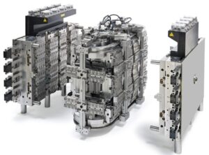
Except for the pin-point entryway utilized with a three-plate mold, all the first gates designs from china mould design services require the expulsion of the feed system from the trim by some post-forming framework (as a rule the administrator). The passage entryway is a typical kind of gate that can be viewed as a variation of the pin-point door. Its essential bit of leeway is that the passage entryway pr0vides for programmed de-gating with the activation of a basic two-plate shape. The plan of a passage entryway for the cover shaping is appeared. Contrasted with the pin point entryway, the progressions have all the earmarks of being corrective with the expansion of certain turns and tightens. These distinctions are irrelevant as for the progression of the plastic dissolve, so the components of the passage entryway ought to be resolved as recently examined to accommodate sensible shear rates and weight drops.

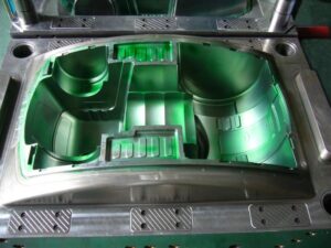
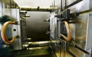
From the outset, the passage gate appears to be fundamentally the same as the pin-point entryway. Nonetheless, they vary altogether in structure and capacity. The capacity of the passage gate can be perceived by looking at the form plan. A cross area through the shut shape with the passage entryway is appeared. The way in to the capacity of the passage entryway is that the passage gate”tunnels” through the pit embed. The embellishment will move away from the depression supplement and remain on the center with the passage door when the shape opens. Simultaneously, the kickoff of the mold powers the passage part of the runner to incidentally stay with the cavity embed. The movement of the center supplement away from the hole embed causes the passage gate to break at its intersection with the embellishment. The embellishment and the feed system would then be able to be launched out as in an ordinary infusion forming measure.

The breadth of the passage entryway at the hole ought to be intended to stay away from unreasonable shear rates and weight drops. For the passage entryway to work dependably, there are two significant points that must be indicated. Initial, an ostensible 45 degree point ought to be kept up between the centerline of the passage door and the splitting plane to take into consideration the transmission of shearing worries to the entryway. Second, the passage door ought to have an included shape point of 20 degrees t0 guarantee that the passage entryway doesn’t stick in the form and that the passage entryway breaks at the intersection with the trim. To guarantee satisfactory auxiliary respectability of the pit undercut, the passage gate ought to be situated in any event three passage measurements off the splitting plane.

The passage gate is a sharp plan since it accommodates programmed de gating without huge venture. The essential danger in application is that the passage entryway might be inappropriately planned or wear with the end goal that lhe runner system doesn’t dependably degate from the trim. T0 help the de-gating of the passage gate from the formed part, the runners ought to be planned with close by sucker pins, to hold the runner system on the center side. In the event that the passage entryways and the runner system stay on the hole side, at that point they can’t be taken out through activation of the discharge system.

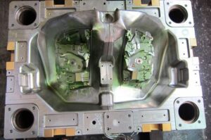
There are a few varieties of the passage entryway for the high-precision molds made in china. Similarly as the passage entryway burtows up into the hole embed, the term”submarine”gate alludes to a plan variation where the passage door slides into the center supplements. The activation of the ejector system and the launch of the embellishment of the center at that point demonstration to break the entryway and strip the feed system from the trim. With both passage and submarine entryways, it is likewise conceivable to configuration expanded gates that bend around vertical side dividers to gate onto the inside surfaces of the part. Such an all-inclusive submarine door configuration, otherwise called a”banana”or”cashew”gate,, however such plans represent extra danger as for solid de-gating.

This article is from https://www.injectionmouldchina.com

Gate

The item and mold designer of mold manufacturer factory will regularly cooperate to decide the gating location(s) in light of numerous elements including the kind of sprinter framework, stylish prerequisites, expected sew line areas, quality and direction contemplations, and dimensional control. By and large, expanding the quantity of entryways will improve shaping profitability and dimensional soundness yet with expanded form unpredictability and more noteworthy number of sew lines.

For instance, consider the screen bezel with the quantity of entryways equalto 1,2,3, or 4. For variety, accept that the plans with 1 and 3 entryways utilize cold sprinters with edge doors into the inner casing of the bezel while the plans with 2 and 4 entryways utilize hot sprinters with warm sprue doors into the back substance of the encompassing edge.

The subsequent filling designs for the different gating alternatives are portrayed. It is seen that for every one of the entryway plans, the polymer liquefy streams radially from the door and afterward changes to a direct stream design. The weave line areas are portrayed as thick lines; the quantity of sew lines increments relatively with the quantity of doors. The stream length is the good ways from the entryway to the sew line. In every one of the gating plans from china mould manufacturing manufacturers, the gating areas have been chosen so every one of the stream length are roughly equivalent.

It ought to be perceived from the depression filling that more drawn out stream lengths will require higher soften pressures. One advantage of utilizing numerous entryways is the capacity to infuse the polymer liquefy all the more rapidly into the depression while keeping up a similar polymer stream rate and shear rate in the Cavity. Appropriately, the recreation utilized a 1 S injection time for the single door plan, 0.5 s for the two entryway plan, 0.33 s for the three entryway plan, and 0.25 s for the four door plan. The subsequent liquefy pressures for every one of the gating plans are appeared in oem/odm 2 shot injection moulding factory. It is seen that every one of the soften pressure accounts are firmly adjusted all through a significant part of the hole filling measure, yet the plans with less doors must have longer occupying occasions and dispatching pressures so as to drive the polymer liquefy t0 the stream length required.

The reproduction results intently follow the outcomes. The single door configuration is likely an unsatisfactory alternative because of the high injection weights of 160 MPa. Besides, the area of the weave line so far fr0m the entryway will probably bring about an extremely feeble sew line on the grounds that the pressing phase of the trim cycle will be probably not going to make up for volumetric shrinkage of the polymer dissolve as it cools. Accordingly, the part is probably going to have exorbitant nonuniform shrinkage, warpage, and an exceptionally frail weave line. Any of the other gating plans will bring about much lower soften pressures and improved part quality.

The determination of the number and area of entryways is basic as for the mold plan and trim efficiency, thus ought to be made with the endorsement of the item fashioner. It is frequently conceivable to improve the item quality with expanded interest in innovation or material expense. As for the bezel, for instance, the presence of the weave lines could be improved through the enlistment warming of the mold surface. On the other hand, all knitlines could be disposed of by eliminating the inward window in the bezel where the screen would dwell. This region could then be focus gated with a solitary sprue, and afterward the inside window reproduced by machining around the edge of the interior edge. While it would acquire extreme work and material costs, such a mold plan technique is technically straightforward.

This article is from https://www.injectionmouldchina.com.

Thermal Gate

The utilization of a hot runner feed system by china molds produce services wipes out the requirement for the embellishment and cooling of a chilly runner. The plan of gates for hot runners  fluctuates considerably from those for cold runners. The essential targets are commonly the equivalent with respect to the shear rate, pressure drop, and tasteful necessities. Notwithstanding, warm entryways in hot runners should likewise give a set attachment that forestalls the condensed plastic dissolve in the hot runner from streaming out of the gate when the shape opens and the set plastic close to the gate is taken out with the embellishment.

One of the most common sorts of gates utilized by china high precision mold manufacturer in hot runners is the pin-point warm entryway framed with an internal”torpedo” .In this plan, a profoundly conductive torpedo is embedded into the spout close to the entryway. The motivation behind the torpedo is to communicate heat from the spout towards the entryway and keep the plastic liquid inside. Normally, at least two holes in the torpedo are utilized to pass on the plastic dissolve in the feed system into the depression. A slender layer of remaining plastic liquefy is utilized to protect the hot torpedo from the virus form dividers.

During the filling stage in precision molds factory, the liquefy pressure from the trim machine increments until the weight inside the torpedo powers any cemented plastic between the torpedo holes and the entryway into the form pit. The soften would then be able to spill out of the hot runner spout, through the openings, and into the form depression much like a customary cold runner feed system. At the point when the stream stops, the warmth move to the shape will make the protecting plastic mostly set, with the plastic around the tip of the torpedo getting hardened. At the point when the form opens, a little annulus of the cemented material will be broken around the torpedo tip. Nonetheless, a slight hardened layer will remain that keeps the spillage of the dissolve from the hot runner to the earth.

The warm pin-point entryway is an astute plan as for its double utilization of the plastic to decrease heat move and structure a strong seal. In any case, it has three critical drawbacks. To begin with, pin-point gates ordinarily have a little entryway measurement. Similarly likewise with traditional pin-point entryways for cold runners, the distance across of the warm gate and its related holes must be intended to give sensible weight drops and shear rates. On account of the little holes, this gate configuration may not be appropriate for shear touchy 0r vigorously filled materials. The subsequent burden is identified with the home of the protecting plastic. After some time, any stale material will corrupt with the possibility to be maneuvered into the stream and pollute the plastic soften, most ordinarily as dark bits in the formed parts.

The habitation of the protecting plastic can likewise cause huge issues when the decay plays out a shading change, since even limited quantities of leftover material may cause shading streaking on hence formed parts. A third weakness of the warm entryway may likewise emerge. Specilically, the set layer must be constrained from the entryway by expanded liquefy pressure toward the beginning of the trim cycle. The size and timing of the liquefy weight may shift marginally from gate to entryway contingent upon entryway resistances, entryway gathering, and gate temperature dissemination.While not an issue in most trim applications, these differences might be risky in accuracy forming applications.

This article is from https://www.injectionmouldchina.com

Edge Gates

The edge gate is a typical sort of door for china mold component machining used to interface a Cold runner to the edge of a form pit. The plan and overhaul of an edge gate for the cup has been recently examined. Another edge gate configuration is appeared. In this plan, the edge door associates with the internal outskirts of the bezel’s supporting edge. Since this door area is interior to the screen get together, any remnant staying after the gate evacuation won’t be seen by the end-client of the trim. In this way, the edge door can and ought to use the full thickness of the adjoining divider segment, and need not be gated underneath the lower surface of the edge.

Contrasted with the pin-point gate, the edge door has enormously diminished shear rates and weight drops. The mold originator of china molds make services can choose the thickness, length, and width esteems as per the requirements of the application. As a rule, the thickness of the edge door, H, ought to be not exactly the divider thickness of the embellishment, however may move toward the thickness of the trim if shear rates are a worry. The width of the gate, W, ought to be not exactly the distance across of the runner yet wide enough to keep away from over the top shear rates. The length of the edge gate ought to be kept to a base, yet long enough to give the embellishment machine administrator access for de-gating with door cutters.

The tab door can be viewed as a variation of the edge gate, wherein a tab is forever added to the trim with the end goal of improved gating. For instance, the edge gate configuration could be tricky since the liquefy streams from the runner into the meager inward casing of the bezel, which can cause untimely freeze-off of the stream and extreme volumetric shrinkage in the encompassing thicker areas. To improve the stream, a tab, rib, or other component is added to the shape depression for the sole motivation behind gating. In this plan from mold manufacturing factory, a rib with a thickness, H, equivalent to the thickness of the ostensible thickness of the part, has been given that associates the runner to the thicker segment of the embellishment outside the slim internal casing, Since the thickness of the tab door is more noteworthy than the thickness of the slender casing, sink will probably create on the top surface. Nonetheless, this issue isn’t huge in this application since this region is covered up by the screen gathering.


Tab gates can be very powerful regarding cost and trim performance. The way in to their adequacy is to set up potential gating territories where their leftovers won’t influence the feel or usefulness of the subsequent moldings. When such gating zones are built up, the form originator should choose whatever tab math and measurements are fitting for the application. Ordinarily the thickness and width are on the request for the ostensible thickness of the part while the length is limited to associate with the nearest accessible runner.

This article is from https://www.injectionmouldchina.com

Branched Runner

The plan of china injection molded parts factory was explicitly expected for the embellishment of semi-crystalline polymers, for example, polyethylene and polystyrene. Analyses were led with runner measurements of roughly 25 mm and process duration in the region of 60 s; the thickness of the skin was around 6 mm. Obviously, the ideal determination of runner distances across will rely upon the material properties, the soften and form temperatures, and the stream rates and process duration. The utilization of interior radiators and protecting layers, (for example, the air holes, 40a and 40b, around the sprue embeds, 39a and 39b, as appeared in high precision plastic injection mould factory) can give more prominent cycle strength, but with expanded plan intricacy. Maybe due to these handling vulnerabilities, the utilization of protected runner systems has diminished with the commoditization of hot runners. All things being equal, protected runners can give great execution with ease; the creator proposes that form fashioners consider their application in future model trim applications.

A potential issue in”naturally balanced”branched runners in mould manufacture factory is stream irregular characteristics because of warm varieties brought about by the stream and related shearing of the liquefy. Notwithstanding the mathematical equalization of the feed system, it has been seen that parts shaped in cavities might be bigger and heavier relying upon their area in the extended feed system. The stream lopsidedness is made by a non-symmetrical shear appropriation inside the laminar plastic liquefy as it moves through the runner system. In particular, in the feed system there is a dispersion of shear rates and temperatures act0ss the sweep of the runner: a hot polymer liquefy at the focal point of the runner is encircled by a layer of all the more exceptionally sheared, more blazing, and lower-thickness plastic soften. At the point when the laminar soften stream arrives at a branch in the runner system, the lower-thickness dissolve stays in its external position, while the more viscous liquefy at the center is part and streams to the contrary side of the branch, 14. This horizontal variety in consistency will cause a non-uniform stream dispersion at the following downstream branch, 16 and 22.

To determine the stream awkwardness during high precision molds china, it is important to wipe out the parallel consistency variety in the polymer soften. One methodology is the”melt flipper”design that forces a level change only before the branch. In particular, the upstream segment, 100, of Fig. 6.29 relates to the essential runner, 12, of Fig. 6.28 while the downstream segment, 104, relates to the optional runner, 14.


Preceding the branch, a stream diverter, 106, powers the soften upwards into the runner augmentation, 102. At the point when the soften in this manner streams down into the runner, 104, the more thick internal center is coordinated to the side of the runner that is inverse the level change. Since the consistency variety is presently conveyed vertically through the runner, the soften stream is adjusted when the downstream runners branch along the side.

oem/odm automotives injection molding factory gives a plan to a lot of supplements to achieve the level change. The cavity embed, 150, and the center supplement, 156, are set at any important intersection between the upstream and downstream runners. An indented pit, 164, and a jutting center, 162, achieve the level change. Since the consistency variety is just reoriented and not killed, the utilization of different level-changing supplements at successive runner branches will restore the stream imbalances. All the more as of late, research has demonstrated that the stream awkwardness and the capacity to control the soften stream is identified with the liquefy rheology and the preparing conditions. Consequently, extra plans have been created to alter the thickness conveyance in the feed system.


Sucker Pin in Mode Design

Three-plate mold designs from china industrial injection moulding suppliers, frequently use sprue pullers, or”sucker pins,”to follow the chilly runner system to the stripper plate upon the launch of the mold. In this example of injection mold service china, the utilization of sucker pins is expected to give adequate ductile power along the sprue with the end goal that exorbitant pliable anxieties break the door between the sprue and trim. Without the sucker sticks, the chilly runner system would go with the depression plates and be hard to eliminate, since the entryways would even now be joined and there is no instrument given on the a plate to discharge the runner system.

Likewise, mold architects from injection mould manufacturers ought to consider the need of sucker pins during the design of two-plate molds. The essential concern is that the cool runner system may stick to the A portion of the form due to either vacuum attractions to the A plate surface or to the hardening of the plastic dissolve to the machine spout at the head of the sprue. On the off chance that the chilly runner system remains with the fixed side of the mold and all the discharge instruments are on the moving side of the form, at that point the runner system can’t be consequently launched out. The embellishment machine administrator will probably need to postpone the trim machine to physically eliminate the runner system. Besides, in the event that the machine is working on a programmed cycle, at that point the trim machine may attempt to close the form with the runner system still in the mold.

To dodge these issues and improve the dependability of the trim activity, sucker pins might be put at different areas along the feed framework. Maybe the most significant sucker pin is the sprue puller, situated at the base of the sprue, which most successfully serves to disengage the sprue from the machine spout and hold the sprue with the moving side of the mold. In this design by china industrial injection moulding manufacturers, the converse mold at the base of the sprue causes an undercut that holds the sprue. This undercut is later sheared off with the forward actuation of the sprue take out pin.

Other sucker pins might be put at different areas along the cool runner system and, if essential, in the mold pits. The design is very like that of the sprue puller. As for the design, it is re-compacted that the breadth of the sucker be somewhat not exactly the distance across of the related sprinter to keep away from expanded cooling times. The stature and tighten edge of the sucker pin ought to be adequate to pull the sprinter off the fixed side of the form without unnecessary material use Or causing clasping of the related ejector pins upon forward actuation. Common statures and tighten points are one a large portion of the sprinter width and 5 degrees, separately.

The usage justifies a concise conversation. In this usage, an ejector pin has been put underneath the sprinter and opened with a converse mold to hold the sprinter until discharge. Contrasted and the implementation gave at right, the utilization of the opened ejector is a lot more straightforward to machine and simpler to keep up. There are two basic issues, notwithstanding. When high precision plastic making mould suppliers china to start with, the pin as indicated distends marginally into the sprinter area. While this projection won’t fundamentally adjust the stream rates or weight drop through the sprinter, there is a slight possibility that it might incidentally cause an undesired interruption or flimsiness in the stream front. Consequently, it is wanted to adjust the head of the ejector pin with the base of the sprinter. Second, if numerous opened ejector pins are utilized to hold and discharge the runner system, at that point the form fashioner should consider the overall arrangement of the undermining openings. In the event that the arrangement of the openings are not controlled and given aimlessly points, at that point the runner system may accidentally tie to the sucker pins at launch in an arbitrary manner, hampering the appropriation of a fully programmed shaping cycle.

This article is from https://www.injectionmouldchina.com

Hot Runner Section

This mold plan methodology of china precision mould manufactory diminishes the measure of machining as well as decreases the plan time and potential for machining or misalignment botches related with coordinating the two sides of a full round runner.

The essential downside related with these non-circular runners from injection mold maker china is that they offer ascent to nonuniform shear rates and shear worries over their cr0SS-segment. For instance, the trapezoidal runner is anything but difficult to machine, however the areas close to the four corners lead almost no stream down the length of the runner, The exhibition of the trapezoidal runner can be improved by adjusting the base surface to kill two of the corners. Notwithstanding, everything these non-circular sorts of runners will require to be marginally bigger and devour extra material to give a similar weight drop as a full round runner.

The recently depicted investigation can be adjusted for use with non-circular runner areas. While the outcomes won’t be as exact concerning a full-round runner, the water driven measurement, Dn, for every runner type can be determined where A section is the cross-sectional territory of the runner and Psection is the border of the crosS-segment of the runner. F0r reference, Table 6.3 gives conditions relating the predefined measurements to the water driven breadth. It ought to be noticed that the conditions in Table 6.3 have been determined accepting a 5 degree tighten point to help with the launch of the runner from the shape. This suspicion takes into account a decrease in the quantity of plan factors.

There is one other runner area that is very basic in hot runner frameworks: the annulus. In particular, numerous hot runner frameworks join valve pins down the length of the spouts to truly close off the entryway as along these lines talked about . In this plan, the polymer liquefy streams between a tube shaped drop and the round and hollow valve pin, framing an annulus.

The polymer liquefy move through an annular area might be firmly approximated by adjusting the condition for gooey stream in a strip. In particular, the width of the strip can be supplanted by the boundary of the mean breadth of the liquefy annulus, while the thickness of the strip is supplanted by the separation between the valve pin and the spout bore. Making these substitutions in Eq. 5.17 outcomes in the accompanying connection between pressure drop and stream rate in an annular segment for a Newtonian liquid. Where Dpin is the breadth of the valve pin and Dbore is the measurement of the drag through the spout. The force law model for an annulus can be correspondingly determined.

One model from high precision molds made in china is to figure the weight drop through a valve-gated spout having a length of 150 mm, a drag width of 10 mm, and a valve pin distance across of 5 mm. Expect a material with a thickness of 100 Pa-s streaming at a pace of 50 cc/s. Subbing these qualities into Eq. 6. 14, the assessed pressure drop. Another model: The essential runner in the three plate shape of Fig. 6.7 has a trapezoidal area. Compute the weight drop through a 120 mm length of essential runner with a width of 6 mm, a profundity of 8 mm, and a 5 degree tighten point. Expect the utilization of ABS with a stream pace of 44 cc/s.

This article is from https://www.injectionmouldchina.com

Runner Volume Calculation

When oem/odm injection mold factory is given the number, lengths, and radii of the feed system, the complete feed system I volume, Vec oral, can be registered as where m is the quantity of various sorts of portions in the feed system,j is a record alluding to a particular kind of sprinter section, N; is the occasions that the sprinter segmentj happens in the feed system, Lj is the length of segmentj, and R, is the span of segmentj. As recently talked about, the form originator ought to limit the absolute volume of the feed system to dodge the creation of abundance material waste or regrind in cool sprinter shape or long habitation times in hot sprinter molds.

The methodology prescribed here is to use imperative based philosophy to legitimately illuminate the base runner system widths given a predetermined limitation on the weight drop. On the off chance that the most extreme weight drop for a segment of the sprinter is indicated as△P。

A trouble with this methodology, notwithstanding, is that the clear thickness, umelt, is a component of the shear rate and the sprinter range. To maintain a strategic distance from iterative assessment of the shear rate and consistency, the force law model can be utilized by oem/odm largest plastic injection molding companies to compute the sweep in a solitary advance.

An issue remains, be that as it may, with respect to what the greatest weight drop ought to be in each section of the feed system. Knowing the detail on the absolute weight drop from the machine nozzle to the depression, different plans can be created to designate the weight drop over each part of the feed system. The easiest methodology is to partition the most extreme weight drop for the whole feed system by the quantity of sections between the spout and the pit. For example, if the polymer dissolve coursed through a sprue, an essential sprinter, and an auxiliary sprinter, and the greatest weight drop for the feed system was 30 MPa, at that point the shape originator could decide to assign a most extreme pressure drop of 10 MPa for every one of the portions of the feed system.

The issue with this methodology, notwithstanding, is that it doesn’t represent the length of each bit of the feed system. An exceptionally short optional sprinter, for example, would be apportioned a similar weight drop as a long essential sprinter. The subsequent plan would be problematic with the breadth being excessively little for the optional sprinter and t0o huge for the essential sprinter.

Another straightforward methodology for oem/odm industrial injection mold factory is to disseminate the weight drop over the feed system with respect to the length of every sprinter section.

where△P: is the most extreme weight drop allotted to sprinter section I with length L, and m is the quantity of sprinter portions between the bay and outlet of the feed system. All things considered, longer sprinter fragments will be permitted a relatively more noteworthy bit of the weight drop through the feed system.

In improving the feed system plan of injection moulding design china, the shape originator needs to accept the stream rates during the filling stage and the normal forced drop. Figure 6.20 additionally shows how the feed system plans will change with the volumetric stream rates during the filling stage. Lower stream rates will bring about lower pres sure drops, which thusly take into account a decrease in the radii and volume of the feed system. Since the real stream rates are controlled by the decay after the form is planned and manufactured, the disintegrate ought to confirm the normal occupy season of the depression with the disintegrate and ascertain the normal stream rates through the feed system. In the event that the stream rates are dubious, at that point the shape fashioner can appraise the direct liquefy speed in the cavity per Eq.5.23 and accept that the stream rate is consistent all through the filling stage.

This article is from https://www.injectionmouldchina.com


Hot Runner Mold

Hot runner molds from China mould produce services factory ought to be considered at whatever point gating adaptability, cycle productivity, and material effectiveness are significant. In a hot runner system, the feed system is encased in a warmed channel with the goal that the plastic stays liquid during the trim cycle. Since the plastic doesn’t cool in a hot runner system, there is no compelling reason for oem/odm industrial mold design factory to plasticize the liquefy that would be needed to fill the feed system,

■inject the material that would fill the feed system, hang tight for the material in the feed system to cool, open the shape a generous add up to eliminate the feed system as in a three-plate form,

■de door the feed system from the shaped items, or

■re-granulate or dispose of the runner system,

For every one of these reasons, it isn’t phenomenal for hot runner molds to work with 20% quicker process durations and 20% less piece material than a traditional two-plate or three-plate cold runner shape. Nonetheless, hot runner molds do require a higher beginning venture than either two-plate or three plate molds and furthermore require hot runner regulators to keep up the soften temperature. While hot runners may appear to build vitality usage [2], the related increases in improved material use and trim profitability give net decreases to add up to vitality costs.

China industrial injection moulding manufacturers give a part through an isometric perspective on a hot runner system. This hot runner configuration incorporates a hot sprue bushing, complex, two drops or “spouts,” four warmer control zones, and different parts. During activity, the material from the embellishment machine’s spout will go down the hot sprue bushing to the essential runner situated in the complex. The dissolve at that point crosses down the length of at least one runners to downstream hot runner spouts. The length of the spout is controlled by the good ways from the centerline of the complex to the gating area of each shape depression.

Contrasted with cold runner plans, the distances across of the runners and drops in a hot runner system might be very enormous, since all the material in the hot runner will in the end be constrained into the shape pits. Since the polymer dissolve isn’t squandered, hot runner system can have enormous runner breadths to accommodate low stream opposition and amazing transmission of the infusion strain to the shape pits. Notwithstanding, excessively huge breadths can allow the material to corrupt in the hot runner and forbid quick change overs between various plastic pitches and hues.

A segment through a hot runner form gathering is appeared. This form configuration accommodates the infusion of the plastic soften into the left and right sides of the PC bezel through a normally offset hot runner system with two drops. As can be watched, an air hole encompasses most of the hot runner system to limit heat move from the warmed complex and spouts to the colder form steel.

During trim, the dissolve pressure applied on the essences of the shape depression and hot runner system will bring about powers that would will in general reason the hole embed and the hot runner system to divert. Push cushions, in some cases machined from titanium, are utilized to move these powers from the hot runner system to the top clip plate while moving a negligible measure of warmth. With hot runner molds, cooling lines or potentially protecting sheets ought to be utilized with the top brace plate to forestall the exchange of noteworthy warmth to the platens of the embellishment machine.

The hot runner system configuration gave is a moderately straightforward plan, which uses warm entryways that will be determined in the following section. In this plan, the hot runner spouts are concentric with the door removed gave in the depression embed. Since the complex will extend with changes in the complex temperature, the complex is permitted to grow and slide over the top surface of the spouts. The complex and spouts are kept up in pressure in the stature bearing to forestall any noteworthy measure of liquid polymer from getting away.

There are a wide range of hot runner system arrangements, including drops that are strung and in any case fit to the complex. Various designs of hot runner manifolds are additionally normal. The straight-bar complex is among the easiest. Two other normal plans incorporate the “H” and”X” complex plans. The”H” complex gives different branches to take care of the polymer dissolve through essential, optional, and even tertiary runners situated on the centerline of the complex as like the plan. The”X” complex uses a more straightforward plan wherein all essential runners exude legitimately from the focal point of the complex at the hot sprue bushing. This plan ordinarily accommodates more productive material usage. On the off chance that various drops are being taken care of, numerous manifolds may likewise be stacked.

Hot runner plans have expanded in multifaceted nature and capacity with designs undeniably more unpredictable that those appeared. Later presents stack molds in which at least two hot runner system are stacked in the shape stature heading to consider augmentation of the form depressions without an expansion in brace weight. Hot runner providers can likewise plan “seven-leg specials” in which the lengths and stretching of a hot runner are hand crafted to accomplish unique application prerequisites, commonly for multigated parts, for example, car body boards. The form originator ought to talk with various hot runner providers to comprehend the advantages and issues related with accessible hot runner system.

This article is from https://www.injectionmouldchina.com

Three Plate Mold

A separated isometric perspective on a completely open three plate mold configuration is given; the view gave does exclude the ejector lodging and related parts, since these are not key to the activity of the three-plate mold. Three-plate molds, the high precision molds made in china are contained three mold areas that move comparative with one another, with each segment comprising of one 0r more plates. The expansion of a subsequent splitting plane between the A plate and the top clip plate takes into consideration sprinters to be situated over the mold cavities and to cross across the width and length of the splitting plane without meddling with the mold holes. Thus, the three-plate mold gives more noteworthy opportunity regard to gating areas and the feed framework mold. An additional advantage is that three-plate mold of high precision plastic injection mould suppliers regularly give programmed partition of the molded parts from the feed system.

China industrial injection mold suppliers give a part through a completely shut three-plate mold. In this plan, the polymer soften streams down the sprue bushing over the thickness of the top clip plate and stripper (or”X”) plate. The polymer dissolve at that point streams along sprinters situated in the splitting plane (alluded to here as the”A-X”parting plane) between the A plate and the stripper plate. Tightened sprues are then used to pass on the soften through the thickness of the A plate and any cavity embed uphold plate t0 the mold holes.

Sprue pullers, likewise known as”sucker pins,” are utilized close to the sprue areas and different bits of the sprinter to guarantee that the feed framework stays with the stripper plate; the mold architect should plan the sucker pins with the end goal that they don’t limit stream. In the feed framework plan, the pins have a little breadth and profundity contrasted with the elements of the essential sprinter. To additionally diminish the stream impediment in the plan of Fig. 6.8, they could be moved further away from sprue bushing.

Mould produce factory gives a segment through a halfway opened three plate mold. Subsequent to trim, the B side of the mold is pulled away from the A side, driving the mold to open at the splitting plane between the An and B plates; the ejector framework, back brace plate, and related parts have been discarded. A spring situated between the A plate and the stripper plate might be utilized to cause early partition of the A-X separating plane. The B side keeps on opening, with the separation between the A and the B plates constrained by the length of a stripper jolt interfacing the A plate to the B plate. The free length of the stripper jolt must be adequate to consider the launch of the molded parts. A run of the mill mold opening separation between the An and B plates is equivalent to two to multiple times the tallness of the molded parts. This separation can be very enormous for molded parts with even moderately shallow centers.

When the length of the stripper jolt is crossed, the A plate will move away from the fixed platen alongside the B plate. The A plate will cross the free length of the stripper jolt for the stripper plate. The free length of this stripper jolt decides the mold opening separation between the A plate and the stripper plate.

Likewise with the A plate stripper jolt, the length of the X plate stripper jolt must be adequate to take into account the expulsion of the feed framework. When the A plate crosses past the free length of the X plate stripper jolt, the stripper plate will move away from the top brace plate alongside the A segment, B segment, and discharge arrangement of the mold.

It gives a segment through a completely opened three plate mold without the ejector system or back clasp plate. During mold activity, the mold opening speed and position must be deliberately decided and controlled to accomplish a productive and completely programmed cycle. On the off chance that the mold opening measurements are not painstakingly determined, at that point the feed framework may not be dependably shot out or the mold can be harmed. To advance the mold activity, the mold opening separations in numerous three-plate molds can be balanced by changing the situation of nuts on the stripper screws or by including washers between the plates and the finishes of the stripper fasteners.

It ought to be noticed that this three plate configuration has been made as minimized as conceivable as for mold opening separations, determination of plate thicknesses, and stripper jolt lengths. Accordingly, it is quick to analyze the plan of the three-plate mold with that of the two-plate mold. The extra plates and parts in the three-plate mold have expanded the stack stature by 44 mm (134 inches) and the mass by 30 kg, moderately little increments (on the request for 20 %). Nonetheless, the three-plate mold has a mold opening separation of 250 mm, a lot more noteworthy than the mold opening separation of 75 mm for the two-plate mold.

This bigger mold opening separation is unwanted, since it adds to the mold opening and shutting time and may likewise keep the mold from working in some infusion molding machines with restricted light.

This article is from https://www.injectionmouldchina.com/