Cooling

As an option in contrast to penetrating cooling lines, cooling lines that adjust to the state of the shape hole can be processed into the back essences of the pit or center embeds as appeared in oem/odm industrial mold factory. For this situation, a ball end factory is directed around the lower part of the center addition, after which interfacing lines are bored aside of the shape. The cooling lines can consequently intently follow the shapes of the formed part, in any event, for bended surfaces. The area of the coolant passageway and ways out has been chosen to adjust the weight drop between the interior and outside circuits.

Despite the fact that the cooling embed configuration appeared in injection tooling factory gives uncommon cooling, it presents potential spillage issues. In this plan, a notch has been furnished and fitted with a gasket. At the point when attached firmly to the help plate, the gasket will forestall spillage outside the form. In any case, spillage ought not out of the ordinary at any ejector pins found inside to the territory encompassed by gasket. In this application, a stripper plate could be effectively utilized as examined in stainless steel metal injection moulding housing manufacturers china.

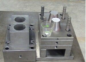
Assembling innovation is proceeding to progress, and generally new shape causing advances to incorporate polyjet [17], stereolithography [18], intertwined testimony displaying (FDM, [19]), and specific laser sintering (SLS, [20]) as immediate metal laser sintering (DMLS, [21]). These 3D printing advances give the capacity to straightforwardly put cooling lines at any area as the center and cavity embeds are being printed. Returning now to the center addition for the cup, a conformal cooling line configuration is given in Fig. 9.17 in which the coolant is directed to the focal point of the supplement and afterward branches to a progression of veins like an inside drinking fountain, in this manner disposing of the temperature slopes appeared in high precision molds china.

Since almost any math can be made with these 3D printing advancements, inside cooling lines of subjective plan can be made to adjust to the cavity surfaces to improve heat move rates and consistency. Huge continuous issues incorporate quality, porosity, and surface completion of the printed embeds. In particular, polymer shape embeds made by polyjet, stereolithography, FDM, and SLS give an ease way to deal with model forms yet have low warm conductivity and quality.

The plan of two shots mould made in china would at present require an all-inclusive process duration contrasted with metal supplements, on the request for 100 s, while being probably not going to endure in excess of a couple dozen trim cycles. Setting the cooling lines further from the form surface would lessen the quality issues, yet refute the advantage of having conformal cooling lines. On the other hand, DMLS additions would give adequate quality as proposed by the survey of material properties depicted by Kruth et al. [20]. Be that as it may, such DMLS supplements would be very costly while not giving adequate surface appearance.

Another way to deal with diminishing temperature angles is to use profoundly conductive addition materials, for example, Cu 940 or Aluminum QC10, for divides or the whole center supplement. Since these materials have a lot higher warm conductivity than steel, their specific use in molds having”hot spots” will in general diminish the temperature variety over the depression. For instance, the anticipated temperature appropriations toward the finish of the trim cycle for the cup center addition utilizing a Cu 940 material are given in Fig. 9.18. Similarly as with the outcomes accommodated a steel center in Fig. 9.11, each mold line speaks to a 2°C change in temperature. The outcomes demonstrate that the temperature inclination has been diminished by around 60% contrasted with the temperature angles appeared in factory injection mould.
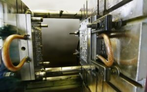

Conductive additions can likewise give improved cooling in the interior corners of moldings. Due to the warmth move in three measurements and constraints with respect to the vicinity of the cooling line to the form divider, the cavity embed for will in general direct considerably more warmth away from the shaped plastic contrasted with the center supplement. The temperature dissemination for a normal plan utilizing a solitary material for both the center and the hole is appeared in Fig. 9.19(a). At the point when the center and pit embeds both comprise of P20, there is a 5°C temperature angle over the divider thickness of the trim. Notwithstanding, onlya 1 °C differential over the divider thickness of the trim happens when the center supplement is determined with Cu 940 as appeared in Fig. 9.19(b).The essential favorable position of exceptionally conductive center supplements is the capacity to deliberately control the warmth stream. While these materials increment the pace of warmth move, their properties are not suitable for use all through the shape. There are two essential reasons. To start with, it ought to be noticed that the improved temperature circulations accomplished in Fig. 9.19(b) were the consequence of utilizing various materials for the center and depression embeds. These temperature conveyances would not have been as uniform if both the center and hole embeds were produced using Cu 940. Second, these profoundly conductive materials will in general have lower hardness and are more powerless to wear. Thusly, exceptionally conductive additions might be best when utilized in applications with high creation volumes, low to direct infusion pressures, and non-rough materials.

This article is from https://www.injectionmouldchina.com
Branched Runner

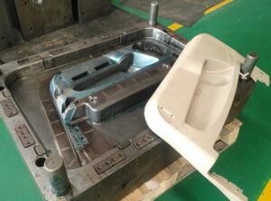
The plan of china injection molded parts factory was explicitly expected for the embellishment of semi-crystalline polymers, for example, polyethylene and polystyrene. Analyses were led with runner measurements of roughly 25 mm and process duration in the region of 60 s; the thickness of the skin was around 6 mm. Obviously, the ideal determination of runner distances across will rely upon the material properties, the soften and form temperatures, and the stream rates and process duration. The utilization of interior radiators and protecting layers, (for example, the air holes, 40a and 40b, around the sprue embeds, 39a and 39b, as appeared in high precision plastic injection mould factory) can give more prominent cycle strength, but with expanded plan intricacy. Maybe due to these handling vulnerabilities, the utilization of protected runner systems has diminished with the commoditization of hot runners. All things being equal, protected runners can give great execution with ease; the creator proposes that form fashioners consider their application in future model trim applications.

A potential issue in”naturally balanced”branched runners in mould manufacture factory is stream irregular characteristics because of warm varieties brought about by the stream and related shearing of the liquefy. Notwithstanding the mathematical equalization of the feed system, it has been seen that parts shaped in cavities might be bigger and heavier relying upon their area in the extended feed system. The stream lopsidedness is made by a non-symmetrical shear appropriation inside the laminar plastic liquefy as it moves through the runner system. In particular, in the feed system there is a dispersion of shear rates and temperatures act0ss the sweep of the runner: a hot polymer liquefy at the focal point of the runner is encircled by a layer of all the more exceptionally sheared, more blazing, and lower-thickness plastic soften. At the point when the laminar soften stream arrives at a branch in the runner system, the lower-thickness dissolve stays in its external position, while the more viscous liquefy at the center is part and streams to the contrary side of the branch, 14. This horizontal variety in consistency will cause a non-uniform stream dispersion at the following downstream branch, 16 and 22.

To determine the stream awkwardness during high precision molds china, it is important to wipe out the parallel consistency variety in the polymer soften. One methodology is the”melt flipper”design that forces a level change only before the branch. In particular, the upstream segment, 100, of Fig. 6.29 relates to the essential runner, 12, of Fig. 6.28 while the downstream segment, 104, relates to the optional runner, 14.


Preceding the branch, a stream diverter, 106, powers the soften upwards into the runner augmentation, 102. At the point when the soften in this manner streams down into the runner, 104, the more thick internal center is coordinated to the side of the runner that is inverse the level change. Since the consistency variety is presently conveyed vertically through the runner, the soften stream is adjusted when the downstream runners branch along the side.

oem/odm automotives injection molding factory gives a plan to a lot of supplements to achieve the level change. The cavity embed, 150, and the center supplement, 156, are set at any important intersection between the upstream and downstream runners. An indented pit, 164, and a jutting center, 162, achieve the level change. Since the consistency variety is just reoriented and not killed, the utilization of different level-changing supplements at successive runner branches will restore the stream imbalances. All the more as of late, research has demonstrated that the stream awkwardness and the capacity to control the soften stream is identified with the liquefy rheology and the preparing conditions. Consequently, extra plans have been created to alter the thickness conveyance in the feed system.


Mould Injection and Ejection

High precision plastic injection mould manufacturers take it as common easy work to view a mold from external and seperated parts. An injection form has numerous structures to achieve the capacities required by the injection shaping procedure. Since there are a wide range of kinds of molds, the structure of a simple”two-plate” form is first examined. It is significant for the shape originator to know the names and elements of the form segments, since later parts will expect this information. The structure of these parts and more perplexing molds will be dissected and planned in ensuing sections. It’s an easy job for china molds produce services suppliers.


Another isometric perspective on the form is appeared, arranged on a level plane for activity with a flat injection shaping machine. In this delineation, the plastic liquefy has been infused and cooled in the shape, with the end goal that the moldings are currently prepared for discharge. To perform launch, the shape is opened by in any event the tallness of the moldings. At that point, the ejector plate and related pins are pushed ahead to push the moldings off the center. From this view, a large number of the shape parts are watched, including the”B”or center addition retainer plate, two diverse center supplements, feed framework, ejector pins, and guide pins and bushings. China standard components for injection mold have the high quality control about all these parts.


This demonstrates that the plastic embellishment comprises of two distinctive shaped parts (like a cup and a cover) connected to a feed framework. This form is known as a two-plate, cold-sprinter, 0r two hole family shape. The term”family form” alludes to a shape where numerous parts of changing shapes and additionally estimates are delivered simultaneously, most regularly to be utilized in an item get together. The term”two-cavity” alludes to the way that the form has two depressions to create two moldings in each trim cycle. Such multi-cavity molds are utilized to quickly and monetarily produce high amounts of shaped items. Molds with at least eight cavities are normal. The quantity of form holes is a basic structure choice that impacts the innovation, cost, size, and unpredictability of the shape; a cost estimation technique is given plan direction. Plastic precision injection mould manufacturers china are very competitive at all these points.

In a multi-cavity shape, the cavities are set over the splitting plane to give room between the form pits for the feed framework, c0oling lines, and different segments. It is commonly wanted to put the shape cavities as near one another as conceivable without yielding different capacities, for example, cooling, discharge, and so forth. To automotive molds made in china, this generally brings about a littler shape that isn’t 0nly more affordable, but at the same time is simpler for the disintegrate to deal with while being usable in all the more trim machines. The quantity of form cavities in a shape can be altogether expanded by utilizing a bigger shape, yet additionally by utilizing various sorts of molds, for example, a hot sprinter form, three-plate shape, or stack form as later talked about as for shape format plan.

This article is from https://www.injectionmouldchina.com.