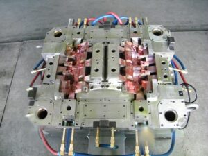
Plastic Molding Distortion

The initial phase in the discharge of the moldings from the mold is to open the shape at least one splitting planes. The mold fashioner should work with the item planner and decay to guarantee that the shape configuration is appropriate and powerful. When all is said in done, the quantity of moving centers ought to be limited by improving the item plan and building up an appropriate shape plan. When moving centers are utilized by china molds design services, they should be planned, whenever the situation allows, to work with the initial activity of the form as opposed to depending on extra actuators and control frameworks.

Now and again the formed part requires a moving center plan that can’t be impelled by the shape opening development. Most current trim machines uphold such”core pull” groupings using advanced signs. After the cooling and plastication stages, when the shape is prepared to open, the trim machine can be customized to give at least one center draw signs to the necessary actuators (commonly pneumatic valves, water driven valves, electric solenoids, or electric engines). The actuators would then be able to withdraw the associated shape parts, which ought to be intended to contact a cutoff switch when completely withdrawn to give a positive input signal that the moving centers are withdrawn and the form is sheltered to open.

The trim machine will normally be modified to postpone the shape opening until all cutoff changes from all center force circuits are stimulated.

For china high precision mold supplier to eliminate the moldings from the shape, discharge powers must be applied to take the moldings off the center surfaces. These discharge powers can be applied by various shape segments including ejector pins, sleeves, sharp edges, lifters, air poppets, stripper plates, and different gadgets. The number, area, and plan of these segments must be created to dependably communicate the powers from the embellishment machine’s take out rod(s) through the launch framework to the plastic moldings. With each discharge cycle, huge shear and compressive powers are applied to the launch framework segments. On the off chance that the segments are inadequately planned, these launch powers may bring about exorbitant shear pressure, compressive pressure, selection, weariness, clasping, and shape disappointment. For instance, the 1se of too hardly any, little pins will cause such high shear stresses to in a real sense poke holes through the shaped section, an imperfection known as push-pin.

Similarly as the launch powers can cause pressure and diversion in the discharge framework segments, the launch powers can likewise cause pressure and redirection in the plastic moldings. To keep away from lasting twisting of the plastic moldings, the number, area, and plan of the ejector parts must be created to apply a low and uniform condition of pressure over the moldings. On the off chance that the ejector power is consistently conveyed across numerous focuses in the form hole, at that point the embellishment will be consistently ejected from the shape with no lasting mutilation.

this article is from https://www.injectionmouldchina.com
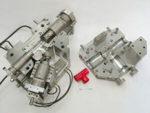
Shrinkage Prediction

PC reenactment is an undeniably basic in plastics item and form plan for china injection molded parts factory, with Autodesk/Moldflow, Core Iech/Moldex3D, and Sigma Engineering/Sigmasoft giving shrinkage assessment to shaped parts. To exhibit the examination for the bezel, Autodesk/Moldlow (Molding Plastics Insight, MPI 2014 [8]) was performed for Cycolac MG47. The isotropic shrinkage rates anticipated by the recreation are given in injection mold services china expecting similar conditions as the earlier investigation: a mid-range liquefy temperature, mid-range coolant temperature, a steady pressing weight of 66 MPa for a period of6 s, and a cooling season of 20 s.

The outcomes demonstrate that the shrinkage changes generally over the form hole. Low shrinkage rates (on the request for 0.3 % and underneath) are anticipated in the slight territories around the edge that freeze at high dissolve pressures. Specifically, the most minimal shrinkage of 0.1 % adjoining the door is anticipated as this region of the hole totally freezes at high soften pressures over 100 MPa while the polymer liquefy is filling the rest of the pit. Moderate shrinkage rates (around 0.6%) are anticipated in the majority of the part, which is more than the 0.31 % shrinkage recently anticipated by the manual investigation. High shrinkage rates (over 1 %) are anticipated close to the furthest limit of fill. The high shrinkage rate toward the finish of fill is because of the way that the material closer the entryway is hardening and forestalling extra polymer liquefy from arriving at the finish of stream to make up for volumetric shrinkage.

The outcomes show a critical issue for the shape planner and the end-client: what shrinkage worth ought to be utilized? In the event that a normal shrinkage of 0.6% is utilized, at that point the part width might be out of detail due to the exorbitant unaccounted shrinkage along the top and base edges.

There are a few unique procedures that can be utilized by the shape planner if nonuniform shrinkage happens. One progressively regular technique, which is upheld by the joint utilization of PC reproduction and CNC machining, is for the form planner to utilize distinctive shrinkage esteems in various parts of the shape. For the PC bezel appeared in oem/odm injection mould factory, the decay may pick a shrinkage estimation of 0.7% for the left and right sides and a shrinkage esteem over 1 % for the top and base sides. In this model, this procedure is moderately simple to utilize and would probably be fruitful since the calculation is generally straightforward. For more unpredictable item calculation with a firmly interconnected surface, in any case, the utilization of non-uniform shrinkage esteems can turn into an intricate and hazardous undertaking.

Another regular way to deal with acquiring tight resistances is to guarantee more uniform shrinkage over the form hole through the expansion of various entryways. By expanding the quantity of entryways for the PC bezel from two to four as appeared in china plastic injection molding, the filling and pressing weights and in this way the shrinkage rate are completely made more uniform over the form pit. In this model, the extra two entryways have diminished the greatest shrinkage from 1.3 % at the focal point of the top edge in Fig. 10.8 to 0.74% at the corners in high precision plastic injection mould factory. Besides, the normal shrinkage in the hole has been decreased from 0.7 % for the twogated shape plan to 0.65% for the four-gated form plan.

Cooling

As an option in contrast to penetrating cooling lines, cooling lines that adjust to the state of the shape hole can be processed into the back essences of the pit or center embeds as appeared in oem/odm industrial mold factory. For this situation, a ball end factory is directed around the lower part of the center addition, after which interfacing lines are bored aside of the shape. The cooling lines can consequently intently follow the shapes of the formed part, in any event, for bended surfaces. The area of the coolant passageway and ways out has been chosen to adjust the weight drop between the interior and outside circuits.

Despite the fact that the cooling embed configuration appeared in injection tooling factory gives uncommon cooling, it presents potential spillage issues. In this plan, a notch has been furnished and fitted with a gasket. At the point when attached firmly to the help plate, the gasket will forestall spillage outside the form. In any case, spillage ought not out of the ordinary at any ejector pins found inside to the territory encompassed by gasket. In this application, a stripper plate could be effectively utilized as examined in stainless steel metal injection moulding housing manufacturers china.

Assembling innovation is proceeding to progress, and generally new shape causing advances to incorporate polyjet [17], stereolithography [18], intertwined testimony displaying (FDM, [19]), and specific laser sintering (SLS, [20]) as immediate metal laser sintering (DMLS, [21]). These 3D printing advances give the capacity to straightforwardly put cooling lines at any area as the center and cavity embeds are being printed. Returning now to the center addition for the cup, a conformal cooling line configuration is given in Fig. 9.17 in which the coolant is directed to the focal point of the supplement and afterward branches to a progression of veins like an inside drinking fountain, in this manner disposing of the temperature slopes appeared in high precision molds china.

Since almost any math can be made with these 3D printing advancements, inside cooling lines of subjective plan can be made to adjust to the cavity surfaces to improve heat move rates and consistency. Huge continuous issues incorporate quality, porosity, and surface completion of the printed embeds. In particular, polymer shape embeds made by polyjet, stereolithography, FDM, and SLS give an ease way to deal with model forms yet have low warm conductivity and quality.

The plan of two shots mould made in china would at present require an all-inclusive process duration contrasted with metal supplements, on the request for 100 s, while being probably not going to endure in excess of a couple dozen trim cycles. Setting the cooling lines further from the form surface would lessen the quality issues, yet refute the advantage of having conformal cooling lines. On the other hand, DMLS additions would give adequate quality as proposed by the survey of material properties depicted by Kruth et al. [20]. Be that as it may, such DMLS supplements would be very costly while not giving adequate surface appearance.

Another way to deal with diminishing temperature angles is to use profoundly conductive addition materials, for example, Cu 940 or Aluminum QC10, for divides or the whole center supplement. Since these materials have a lot higher warm conductivity than steel, their specific use in molds having”hot spots” will in general diminish the temperature variety over the depression. For instance, the anticipated temperature appropriations toward the finish of the trim cycle for the cup center addition utilizing a Cu 940 material are given in Fig. 9.18. Similarly as with the outcomes accommodated a steel center in Fig. 9.11, each mold line speaks to a 2°C change in temperature. The outcomes demonstrate that the temperature inclination has been diminished by around 60% contrasted with the temperature angles appeared in factory injection mould.


Conductive additions can likewise give improved cooling in the interior corners of moldings. Due to the warmth move in three measurements and constraints with respect to the vicinity of the cooling line to the form divider, the cavity embed for will in general direct considerably more warmth away from the shaped plastic contrasted with the center supplement. The temperature dissemination for a normal plan utilizing a solitary material for both the center and the hole is appeared in Fig. 9.19(a). At the point when the center and pit embeds both comprise of P20, there is a 5°C temperature angle over the divider thickness of the trim. Notwithstanding, onlya 1 °C differential over the divider thickness of the trim happens when the center supplement is determined with Cu 940 as appeared in Fig. 9.19(b).The essential favorable position of exceptionally conductive center supplements is the capacity to deliberately control the warmth stream. While these materials increment the pace of warmth move, their properties are not suitable for use all through the shape. There are two essential reasons. To start with, it ought to be noticed that the improved temperature circulations accomplished in Fig. 9.19(b) were the consequence of utilizing various materials for the center and depression embeds. These temperature conveyances would not have been as uniform if both the center and hole embeds were produced using Cu 940. Second, these profoundly conductive materials will in general have lower hardness and are more powerless to wear. Thusly, exceptionally conductive additions might be best when utilized in applications with high creation volumes, low to direct infusion pressures, and non-rough materials.

This article is from https://www.injectionmouldchina.com
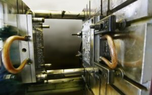
Polymer Flow in Mold Making

To break down the polymer stream in china plastic injection molding, it is important to comprehend the connection between the shear pressure, shear rate, and consistency. The shear pressure, T, is a proportion of how much power per unit zone is being applied by the liquid as it streams. The shear rate, I, is a proportion of the rate at which the soften speed changes. The shear pressure is identified with the shear rate through the thickness, 7, which is a proportion of the liquid’s protection from stream.

Consider the stream between a moving plate and a fixed plate appeared in china high precision mold supplier, Expecting that the stream is completely evolved and doesn’t slip at the dividers, at that point a direct speed profile is seen over the liquid with the speed, v, equivalent to zero at the fixed divider and equivalent to V at the moving plate. For a stream between one tationary and one moving equal plate, the shear rate is characterized as the adjustment in the speed through the thickness.

The weight drop brought about by the progression of the polymer dissolve in a channel can be broke down by thinking about the condition of movement. For consistent stream, the whole of the powers m11st ec11al to zero .

Consider the powers acting along the side on the stream in a rectangular direct as appeared in Fig. 5.3. As the stream moves from left to right, there will be a weight drop along the stream with P1 being more noteworthy than P2. This weight drop is being brought about by the gooey stream in the channel that is producing shear stresses, T, against the side dividers. There are two powers on the polymer soften that must adjust. To start with, there is the power because of the weight drop, Fxp, over the length of the liquefy stream. Second, there is the power because of the shear stresses, F, following up on the top and base surfaces along the length. Likening the power because of the weight drop and the power because of the shear stresses Provides Let dP/dL be the weight drop per unit length. Improving at that point gives the accompanying outcome.

To register pressure drop as an element of the thickness, it is important to characterize the consistency as an element of the shear rate and temperature so the shear stresses can be figured.

The expression “rheology” alludes to the investigation of distortion and stream of issue [2, 3]. The term”viscosity” alludes to the obstruction of a liquid as it distorts under. Shear focuses and is characterized by Eq. 5.1 as the shear pressure separated by the shear rate.

The consistency conduct of polymer melts in oem/odm industrial injection moulding factory can be very mind boggling, considerably more so than is frequently refreshing when experts mull over liquefy stream files (MFI). The liquefy stream record, characterized by ASTM D1 238, gauges what number of grams of polymer move through a fine of a predetermined length and width given a predefined measure of weight and time. A higher liquefy stream list typically compares to a lower consistency and improved simplicity of handling. Notwithstanding, the MFI is a solitary point gauge of the thickness and isn’t characteristic of the material conduct over the wide scope of shear rates, temperatures, and weights when it is being formed. Therefore, better thickness models are applied to injection forming by china injection mould maker.

The Cross WLF model [5] is generally known as a competent model of the liquefy thickness, η, as an element of shear rate, I, temperature, T, and weight, P.In this model, no is the”Newtonian limit” in which the consistency moves toward a consistent at exceptionally low shear rates, τ* is a basic feeling of anxiety at which the thickness advances from as far as possible to the force law system, and η is the force law record in the high shear rate system. The type of the Cross model is promptly reasonable since these three boundaries, 7o,τ*, and η, can be assessed legitimately from a log-log plot of the thickness as an element of shear rate as appeared in Fig. 5.4.

In the Cross model, the zero shear thickness, no, is itself a component of temperature, T, and weight, P. The temperature reliance can take numerous structures, including the Arrhenius connection [6]. Another basic model was first portrayed by Williams, landel, and Ferry (WLF) [7] that incorporates pressure reliance through the moving of the glass change temperature, T*. The model boundaries (n, r*, D, D2, D3, A1, A3) are normally controlled by bend fitting exploratory shear-consistency information taken by a narrow rheometer at shear rates from 1 to 10,000 1/s. The material properties for a large number of plastic pitches have been portrayed, and the Cross-WLF model coefficients for some delegate materials are given in Appendix A. The Cross-WLF consistency model for a medium thickness PC is plotted as a component of shear rate for three distinct temperatures in Fig. 5.5. The thickness displays a Newtonian lateau for shear rates up to 100 1/s, at that point changes into a force law system. For a liquefy temperature of 280°C, the thickness diminishes from 350 Pa.sat 100 1/sto 80 Pa.s at 10,000 1/s. Since the thickness is firmly reliant on the shear rate, assessment of the occupying time, dissolve speed, and shear rate are essential to the investigation forecasts. The thickness is likewise a solid capacity of temperature, with the zero shear consistency expanding from 250 Pa.s at 290°C to 660 Pa.s at 270°C. In this way, information on the handling temperature is likewise critical to foreseeing the soften stream and weight. While the Cross WLF model is an exceptionally capable model and is ordinarily utilized in mathematical recreation, it isn’t as valuable in manual illing investigation. The issue is that it is hard to work and not managable to diagnostic arrangement of the weight as an element of the soften stream rate. Hence, a few other thickness models are ordinarily utilized that have moderately straightforward systematic arrangements.

This article is from https://www.injectionmouldchina.com
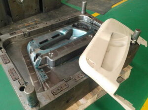
Different Molds in Molding Factory

Here is to list some of different molds in Precision plastic injection mold factory .

Hot runner molds give the advantages of three plate molds without their hindrances, yet offer ascent to different issues. The term”hot runner” is utilized since the feed framework is ordinarily warmed and S0 stays in a liquid sculpture all through the whole trim cycle. Subsequently, the hot runner doesn’t devour any material or process duration related with passing on the soften from the trim machine to the form holes.

A segment of a multi-gated single cavity form is given. This form contains a solitary pit, which is intended to deliver the front lodging or”bezel” for a PC or tablet PC. The hot runner framework incorporates a hot sprue bushing, a hot complex, and two hot runner spouts just as warmers, cabling, and different parts related for warming. The hot runner framework is deliberately intended to limit the warmth move between the hot runner framework and the encompassing mold using air holes and insignificant contact territory. Like the three plate shape plan, the essential and optional runners are steered in the complex over the form cavities to accomplish adaptability in gating areas. Since the polymer liquefy remains liquid, hot runners can be intended to give bigger stream exhausts and amazing weight transmission from the embellishment machine to the shape holes. In that capacity, hot runner framework can encourage the trim of more slender parts with quicker process duration than either two-plate or three plate molds, while likewise dodging the piece related with cold runners. China custom mold components will be molded in different ways.


During the embellishment procedure, the material infused from the machine spout into the hot sprue bushing pushes the current material in the hot runner framework into the shape hole. At the point when the form pits fill, the hot runner’s warm doors are intended to set and forestall the spillage of the hot polymer dissolve from inside the hot runner framework to the outside of the shape when the form is opened. The dissolve pressure created inside the hot runner framework toward the beginning of the following trim cycle will make these warm doors break and permit the progression of the polymer liquefy into the form cavity.


There are a wide range of hot runner and gating structures for the pp joint fitting mould manufacturers that can give points of interest that incorporate gating adaptability, improved weight transmission, decreased material utilization, and expanded trim efficiency. Be that as it may, there are likewise at any rate two noteworthy disservices. To begin with, hot runner frameworks require included speculation for the arrangement and control of the hot runner temperature. The additional speculation can be a huge part of the complete form cost, and not all decays have the helper gear or aptitude to work and keep up hot runner molds. The second inconvenience of hot runner frameworks is broadened change over occasions related with the cleansing of the contained polymer liquefy. In short run creation applications having stylish necessities, the quantity of cycles required to fire up or change pitches or even shading might be unsuitable.

This article is from https://www.injectionmouldchina.com.