Klarm Mould Provides Competitive Molding Service

Attachment head cap screws are the most well-known latches utilized in molds. A %”13 attachment head cap screw is appeared in Fig. 12.32. The essential explanation is that attachment head cap screws have been deliberately planned [12] to enhance the exhibition of the head, strings, and fastener as a framework. In like manner, the attachment head cap screw gives a norm and efficient technique for holding numerous parts along the screw’s hub in injection mould tooling china.

The sizes and burden conveying capacity of attachment head cap screws are identified with their size, material, and medicines. Investigation of standard attachment head screw plans demonstrates that the head tallness is equivalent to the string width, and that the head distance across is around 150% of the string breadth. While the strength of the latch changes to some degree with the coarseness of the string, the rigidity of standard DIN/ISO screws can be genuinely very much assessed by accepting an extreme pressure, ultimate, of 800 MPa duplicated by the cross-sectional zone of the external string width.
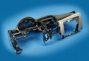
Indicate the size of the attachment head cap screws used to secure the fixed and moving parts of the PC bezel mold. Since this attachment head cap screw is utilized in a basic application of high-precision mould china where disappointment may bring about loss of gear or life, a most dire outcome imaginable is expected.

To begin with, the most extreme mass of the form is assessed accepting a strong square of steel as indicated by the measurements gave in Fig. 12.7.

Then, the most dire outcome imaginable is expected. The most dire outcome imaginable happens when the shape is braced to just one side of the trim machine without the help of the moving platen, which may happen when the form is being introduced in the embellishment machine. Besides, the most dire outcome imaginable will expect that the whole mass of the shape should be upheld by just one fixed screw, which may happen if the other cap screws are not fixed or fixed to lesser sums. The subsequent burden case is appeared in Fig. 12.33.

The applied power on the screw by the form can be assessed by adding the minutes about the finding ring.

Cap screws ought not be depended upon to find form segments given their moderately huge spiral clearances. As recently examined, an obstruction fit ought to be utilized to find one part inside the pocket of another. For equal plates or stacked parts, in any case, dowels or other finding pins ought to be utilized as demonstrated in Fig. 12.34. In this plan, concentric openings are given into the coplanar surfaces of the two plates. A dowel at that point mates with the two openings to find the two parts along the pivot of the dowel.

Assembling differences in the openings’ area, width, and roundness limit the capacity to exactly find the two parts comparative with one another. Condition 12.28 can be utilized for different sorts of fits by fluctuating the cutoff cofficients, C, for the dowel and openings as per global guidelines. Table 1 2.2 gives Coefficients to a locational-leeway fit (LC1), locational-momentary fits (LT1 and LT3), just as the loosest locational-impedance fit (LN1). Locational freedom fits are planned for parts that are commonly fixed yet can be promptly dismantled and reassembled. This fit gives similar request of resistance as strung latches, so isn’t suggested for injection molds since the huge freedom can permit sped up wear of sliding surfaces. Locational-progress fits accommodate more tight control of area, yet with the chance of impedance between the dowel and the opening which upsets the shape get together.

This article is from https://www.injectionmouldchina.com
Klarm Mold Provides Qualified Injection Molding

Another basic issue with deep core is inordinate redirection or”core twisting” because of varieties in the soften pressure around the fringe of the center. The variety in liquefy pressure is regularly because of side gating as demonstrated in Fig. 12.27. Notwithstanding, slight varieties in dissolve stream can cause huge twisting in focus gated plans when the centers are thin (e. g., a center length on the request for multiple times the center breadth). The issue is compounded by the way that the core bending impact is self-supporting, which implies that a slight bending of the core encourages more soften stream and strain to the thicker part of the pit and further bowing of the core during injection moulding services china.

Center twisting can be investigated through fitting utilization of bowing conditions. Regularly, the center is held to the moving side of the mold, and the highest point of the center is allowed to twist.

The size of the pressing factor distinction around the center will shift with the calculation of the embellishment application. A more limited center, similar to that appeared in Fig. 12.27, will have a pressing factor contrast that is a critical part of the compel needed to fill the shape (maybe 50 % of the filling pressure). As the center turns out to be longer comparative with its distance across, the pressing factor contrast around the center will turn out to be less contrasted with the pressing factor distinction along its stature (maybe 10% of the filling pressure). Be that as it may, the center avoidance is relative to the fourth force of the center stature, so a little lopsidedness of the liquefy pressing factor can cause a huge redirection.

Normally, core bending in china industrial injection mold manufacturers turns out to be substantially more critical as the center turns out to be more slim. To limit center twisting, the form fashioner ought to use strong centers with an insignificant length to breadth proportion. Whenever the situation allows, slim center pins ought to be interlocked with the fixed side of the form as demonstrated in Fig. 1 2.28. Such interlocking of the center pin lessens the sidelong diversion of the pin to roughly 10% of the redirection for a pin that is upheld on just one end. When interlocking or expanding the size of the center is obliged by the math necessities of the trim application, the shape architect ought to emphatically suggest utilizing a middle entryway at the highest point of the corner or two contradicting doors at the lower part of the center to limit the pressing factor inclination applied on the center.

Figure 12.30 shows the utilization of stream pioneers by china injection mold maker as another way to deal with lessen the center redirection. In this plan, the stream chiefs will help the soften to go down the depression with lower filling pressures. Simultaneously, the dissolve will proliferate into the more slender neighboring segments of the pit and halfway freeze, subsequently keeping the center from avoiding a huge sum regardless of whether critical pressing factor contrasts emerge later in the filling stage. The stream chiefs appeared on the center in Fig.12.29 might be bothersome as bulges on the inward surface of the formed part, particularly for applications including contact with liquids. Thusly, the stream chiefs might be coordinated outwardly surface of the trim as per an assortment of plan arrangements set into the cavity embed. Obviously, center bowing can be extraordinarily decreased by utilizing various entryways on inverse sides of the center pin or by utilizing a ring door at the lower part of the center pin.

In some mold plans of injection mould manufacturers in china, the core is counterbalanced so then the soften is infused, the center pin avoids to deliver a uniform divider thickness. This idea is like providing”windage”to make up for warpage. The achievement of this system will rely upon the nature of the shape configuration, yet will stay touchy to changes in the plastic gum and handling conditions that influence the liquefy pressing factor and stacking on the center pin.

This article is from https://www.injectionmouldchina.com/


Warpage Prediction

At the point when the embellishment comprises of a solitary shut zone, the material inside the trim is in constant contact with the end goal that any nonuniform shrinkage and stresses over the part may just be settled all through of plane twisting of the part. Injection mould manufacturers in china know that such warpage requires clasping of the plane of the part, which can happen when: (S edge一 S center)> 0.44. (h/W) (h/W)

where h is the divider thickness of the trim, and Scenter and Sedge are the shrinkage rates at the middle and edge of the part, and W is the good ways from the middle to the edge of the embellishment. This clasping examination models the embellishment as an isotropic roundabout plate under uniform outspread edge pressure with a clasping pressure limit of.

As the past warpage investigations have appeared, warpage is brought about by nonuniform shrinkage because of temperature inclinations through the divider thickness of the formed part, pressure angles over the territory of the shaped part, or temperature slopes aCross the zone of the shaped part. These are the most widely recognized reasons for warpage, and have been treated by high-precision mould china with the least complex conceivable examination. In any case, there are different reasons for nonuniform shrinkage including direction and remaining pressure. For additional data, the intrigued form fashioner is alluded to the examination writing.

Sensibly exact warpage forecasts may likewise be gotten with PC recreation as recently talked about. oem/odm largest plastic injection molding companies gives the warpage forecast from PC recreation for the reproduction portrayed for Fig. 10.8. The outcomes recommend that the center of the part will bow down while the left and right sides of the bezel will bow upwards. The purpose behind this conduct is the upper surface of the bezel contains more material, and this upper surface is contracting not exactly the lower part of the ribs.

Given that warpage can be huge contrasted with shrinkage, shape fashioners may decide to make up for warpage by invert biasing the form surfaces dependent on anticipated or noticed warpage. This predisposition is some of the time alluded to as “Kentucky windage,” a shooting term that alludes to the changes a separation shooter must make to represent the breeze [26]. In this manner, Kentucky windage in form configuration alludes to the shaping of the form cavity surfaces with the end goal that after twisting the formed part smoothes to the ideal shape. The utilization of such predisposition isn’t without discussion, since it acquires cost in the forming of shape cavity surfaces while likewise intrinsically changing the warpage and auxiliary conduct of the formed parts. Therefore, it stays a to some degree uncommon practice in oem/odm medical injection mold factory.

Break down warpage accepting that the cup top is focus gated and shaped with ABS at a pressing weight of 66 MPa at the focal point of the part and 0 MPa at the external edge. To assess the warpage, it is first important to compute the shrinkage rates and check the clasping basis. Given the 66 MPa pressing weight and a temperature of 132°C, the straight shrinkage at the middle will be 0.3 1% at the middle. At the edge, the weight of 0 MPa and temperature of 132°C gives a direct shrinkage of 1.66 %. Given that the cup is 2 mm in thickness and 81 mm in breadth, the clasping measure is expressed.

This article is from https://www.injectionmouldchina.com
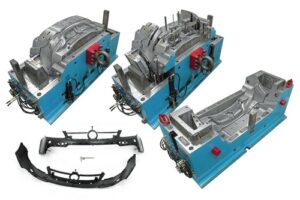
Shrinkage Prediction

PC reenactment is an undeniably basic in plastics item and form plan for china injection molded parts factory, with Autodesk/Moldflow, Core Iech/Moldex3D, and Sigma Engineering/Sigmasoft giving shrinkage assessment to shaped parts. To exhibit the examination for the bezel, Autodesk/Moldlow (Molding Plastics Insight, MPI 2014 [8]) was performed for Cycolac MG47. The isotropic shrinkage rates anticipated by the recreation are given in injection mold services china expecting similar conditions as the earlier investigation: a mid-range liquefy temperature, mid-range coolant temperature, a steady pressing weight of 66 MPa for a period of6 s, and a cooling season of 20 s.

The outcomes demonstrate that the shrinkage changes generally over the form hole. Low shrinkage rates (on the request for 0.3 % and underneath) are anticipated in the slight territories around the edge that freeze at high dissolve pressures. Specifically, the most minimal shrinkage of 0.1 % adjoining the door is anticipated as this region of the hole totally freezes at high soften pressures over 100 MPa while the polymer liquefy is filling the rest of the pit. Moderate shrinkage rates (around 0.6%) are anticipated in the majority of the part, which is more than the 0.31 % shrinkage recently anticipated by the manual investigation. High shrinkage rates (over 1 %) are anticipated close to the furthest limit of fill. The high shrinkage rate toward the finish of fill is because of the way that the material closer the entryway is hardening and forestalling extra polymer liquefy from arriving at the finish of stream to make up for volumetric shrinkage.

The outcomes show a critical issue for the shape planner and the end-client: what shrinkage worth ought to be utilized? In the event that a normal shrinkage of 0.6% is utilized, at that point the part width might be out of detail due to the exorbitant unaccounted shrinkage along the top and base edges.

There are a few unique procedures that can be utilized by the shape planner if nonuniform shrinkage happens. One progressively regular technique, which is upheld by the joint utilization of PC reproduction and CNC machining, is for the form planner to utilize distinctive shrinkage esteems in various parts of the shape. For the PC bezel appeared in oem/odm injection mould factory, the decay may pick a shrinkage estimation of 0.7% for the left and right sides and a shrinkage esteem over 1 % for the top and base sides. In this model, this procedure is moderately simple to utilize and would probably be fruitful since the calculation is generally straightforward. For more unpredictable item calculation with a firmly interconnected surface, in any case, the utilization of non-uniform shrinkage esteems can turn into an intricate and hazardous undertaking.

Another regular way to deal with acquiring tight resistances is to guarantee more uniform shrinkage over the form hole through the expansion of various entryways. By expanding the quantity of entryways for the PC bezel from two to four as appeared in china plastic injection molding, the filling and pressing weights and in this way the shrinkage rate are completely made more uniform over the form pit. In this model, the extra two entryways have diminished the greatest shrinkage from 1.3 % at the focal point of the top edge in Fig. 10.8 to 0.74% at the corners in high precision plastic injection mould factory. Besides, the normal shrinkage in the hole has been decreased from 0.7 % for the twogated shape plan to 0.65% for the four-gated form plan.

Mold Surface Treatment

While determining the material for different form segments, the mold originator ought to likewise think about the consistency of the stock material just as its capacity to be done and treated. Most metals are projected and therefore rolled/framed/cut to their provided mold. The subsequent grain structure and properties are an unpredictable capacity of the constitutive alloying components as well as the warm and auxiliary history during handling. Form creators, mold producers, and end-clients ought to know that there are numerous issues, for example, porosity (voids), contaminants, inhomogeneity, and leftover pressure that may affect the nature of the machined mold.

Consequently, it is suggested that the mold segments be machined from strengthened or standardized steel with negligible lingering pressure and uniform properties. These medicines can accommodate lower hardness and quicker machining. After the mold has been machined and completed by injection moulding china company, the completed part / injection molded parts china may again be toughened to confirm dimensional stabillity and afterward carburized (otherwise called case solidifying) to improve surface hardness by expanding the carbon content at the that are accessible including nitriding, boriding, plating, fume testimony, anodizing, and others. Here gives a correlation of a few surface medicines that might be chosen for explicit application-explicit purposes including expanded hardness, decreased coefficient of contact (COF), hardness, improved consumption opposition, and others.

In many applications, mold creators of injection molding service china will re-appropriate the mold segments to be treated by specialist co-ops that have practical experience in surface medicines. These medicines will expand the underlying buy cost of the mold yet can significantly build the life span and diminish related support costs, particularly when preparing grating saps or long creation runs. Disintegrates likewise frequently depend on surface medicines to determine issues, for example, improving lubricity of form surfaces to ease part discharge, diminish wear between sliding segments, fix scratches, or improve the outside of welded areas. Dissemination measures (e. g., carburizing, nitriding) don’t develop the thickness of the mold surface instead of coatings, which may include considerable mass.

Form architects and mold creators should observe the thickness and consistency of the applied covering, so pit divider thicknesses are intended to give a recompense to its thickness as suitable. Luckily, numerous coatings might be stripped and reapplied if fix or changes in surface properties are required.

The fomold format configuration measure incorporates the assessment of the part calculation to be molded to distinguish the splitting line, separating plane, and shut-offs. The center and hole embeds are then measured and found comparative with one another. A short time later, an appropriate form base is picked or planned that can effectively hold and backing the center and depression embeds. The mold format measure gets done with the choice of the materials utilized for the mold base just as the center and hole embeds. In many high precision plastic making mould china, these materials are promptly requested simultaneously with the nitty gritty investigation and plan of the form subsystems.

We gives a mold structure agenda to elite, standard, and fundamental mold; the subtleties are introduced. The following section looks at the mold pit filling measure, which is needed to 1) confirm that the part configuration can be created at accessible liquefy weights, and 2) gauge the stacking that will be put on the form segments. A short time later, the investigation and structure of the feed framework will be tended to.

This article is from https://www.injectionmouldchina.com/