Klarm Mold Provides Qualified Injection Molding

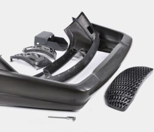
Another basic issue with deep core is inordinate redirection or”core twisting” because of varieties in the soften pressure around the fringe of the center. The variety in liquefy pressure is regularly because of side gating as demonstrated in Fig. 12.27. Notwithstanding, slight varieties in dissolve stream can cause huge twisting in focus gated plans when the centers are thin (e. g., a center length on the request for multiple times the center breadth). The issue is compounded by the way that the core bending impact is self-supporting, which implies that a slight bending of the core encourages more soften stream and strain to the thicker part of the pit and further bowing of the core during injection moulding services china.

Center twisting can be investigated through fitting utilization of bowing conditions. Regularly, the center is held to the moving side of the mold, and the highest point of the center is allowed to twist.

The size of the pressing factor distinction around the center will shift with the calculation of the embellishment application. A more limited center, similar to that appeared in Fig. 12.27, will have a pressing factor contrast that is a critical part of the compel needed to fill the shape (maybe 50 % of the filling pressure). As the center turns out to be longer comparative with its distance across, the pressing factor contrast around the center will turn out to be less contrasted with the pressing factor distinction along its stature (maybe 10% of the filling pressure). Be that as it may, the center avoidance is relative to the fourth force of the center stature, so a little lopsidedness of the liquefy pressing factor can cause a huge redirection.

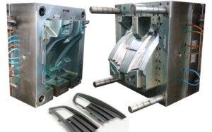
Normally, core bending in china industrial injection mold manufacturers turns out to be substantially more critical as the center turns out to be more slim. To limit center twisting, the form fashioner ought to use strong centers with an insignificant length to breadth proportion. Whenever the situation allows, slim center pins ought to be interlocked with the fixed side of the form as demonstrated in Fig. 1 2.28. Such interlocking of the center pin lessens the sidelong diversion of the pin to roughly 10% of the redirection for a pin that is upheld on just one end. When interlocking or expanding the size of the center is obliged by the math necessities of the trim application, the shape architect ought to emphatically suggest utilizing a middle entryway at the highest point of the corner or two contradicting doors at the lower part of the center to limit the pressing factor inclination applied on the center.

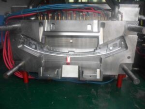
Figure 12.30 shows the utilization of stream pioneers by china injection mold maker as another way to deal with lessen the center redirection. In this plan, the stream chiefs will help the soften to go down the depression with lower filling pressures. Simultaneously, the dissolve will proliferate into the more slender neighboring segments of the pit and halfway freeze, subsequently keeping the center from avoiding a huge sum regardless of whether critical pressing factor contrasts emerge later in the filling stage. The stream chiefs appeared on the center in Fig.12.29 might be bothersome as bulges on the inward surface of the formed part, particularly for applications including contact with liquids. Thusly, the stream chiefs might be coordinated outwardly surface of the trim as per an assortment of plan arrangements set into the cavity embed. Obviously, center bowing can be extraordinarily decreased by utilizing various entryways on inverse sides of the center pin or by utilizing a ring door at the lower part of the center pin.

In some mold plans of injection mould manufacturers in china, the core is counterbalanced so then the soften is infused, the center pin avoids to deliver a uniform divider thickness. This idea is like providing”windage”to make up for warpage. The achievement of this system will rely upon the nature of the shape configuration, yet will stay touchy to changes in the plastic gum and handling conditions that influence the liquefy pressing factor and stacking on the center pin.

This article is from https://www.injectionmouldchina.com/


Final Shrinkage

The disastrous the truth is that to china mould manufacturing manufacturers, the specific shrinkage won’t be known before the shape is planned, manufactured, and tried. The objective in the setting up the last shrinkage proposal

■to give a shrinkage esteem that is near the real shrinkage of the material,

■to furnish a form machined with a shrinkage esteem that might be worked under a scope of cycle conditions to bring the part measurements inside particular, and

■to give a form that is machined”steel safe” with the end goal that the shape can be promptly adjusted if important to bring the part inside determinations.

The introduced shrinkage investigation should give sensible shrinkage gauges given legitimate dissolve temperatures and soften pressures. In any case of plastic injection moulded components china, the assessed contract age can differ broadly given vulnerability about material properties and handling conditions. Therefore, the shrinkage investigation ought to be considered as supplementing different wellsprings of data about shrinkage, The shrinkage examination ought not be utilized in disconnection given the potential for blunder. Notwithstanding, the shrinkage examination ought to be utilized to confirm the shrinkage gauges coming from different sources.

There are a few normal wellsprings of shrinkage information that might be utilized (notwithstanding examination) to help  plastic injection mold manufacturers china with setting up the last shrinkage proposal. Most ordinarily, a material provider or other testing research center may shape parts in a standard test form to assess the shrinkage. Commonly, the test form comprises of a 2 or 3 mm thick plaque that is shaped at mid-range dissolve temperatures and weights. The formed parts are then permitted to equilibrate for quite a while before their measurements are estimated and the straight shrinkage determined. This shrinkage data, when accessible, is generally precise since the testing was led for the specific material of interest at conditions near most embellishment applications. In any case, the gave shrinkage information may not be exact if the divider thickness or handling states of the embellishment application differ essentially from that of the test shape.

One critical issue with shrinkage information from a material provider is that the shrinkage information may not be founded on testing of the genuine material by high-precision molds made in china, but instead suppositions that the material will carry on as evidently comparative materials that have been recently tried. A more costly however more precise option is to configuration, assemble, and test a model shape that has a stream length, divider thickness, and cooling framework like the particular embellishment application. Such model embellishment gives dissolve weights and temperatures that ought to be fundamentally the same as those of the last creation form, so the shrinkage saw with the model shape should be near the last production form. While the advancement of a model shape can be costly, the exactness of the shrinkage estimations can be helpful in close resilience applications.

Another choice is to depend on shrinkage information from past form plans and decay insight. Much of the time, molds may as of now have been planned and worked for creation of moldings that are fundamentally the same as the current form plan application. In such cases, the mold originator of injection molding service china may acquire the best gauges by contrasting the estimations of the moldings and those of the shape steel measurements.

Before making last proposals, in any case, the shape originator ought to ask with the decay to check if the disintegrate would have liked to work the trim machine at various liquefy temperatures as well as weights. Provided that this is true, the form originator ought to ask the disintegrate to create moldings at the favored conditions (regardless of whether the moldings fall outside of determination), and afterward ascertain the shrinkage of these moldings for use in shape plan applications.

A fourth choice is to perform modern PC reenactment of the mold filling, pressing, and cooling stages to foresee the straight shrinkage in the trim application. While PC reproduction uses further developed material science and gives more definite outcomes than the shrinkage examination introduced here, the PC reenactment is as yet dependent upon similar mistakes with respect to the expected material conduct and preparing conditions. Nonetheless, the mathematical recreation can be important to approve the manual shrinkage examination while giving nonuniform shrinkage gauges over the shape pit.

In building up the last shrinkage suggestion, the form architect ought to play out the introduced shrinkage investigation and affirm the outcomes with information from the material provider and past experience, if accessible. On the off chance that the shrinkage rate is dubious, at that point the shape fashioner ought to discuss the expected blunder with the disintegrate, material provider, and end-client to diminish the vulnerability and survey obligation should the used shrinkage rates be so incorrect to bring about expensive form changes. In certain agreements, the last shrinkage proposal is the duty of the form’s client who eventually pays for the expense of the shape plan and any slip-ups. In different cases, no gathering might be happy to acknowledge duty regarding a questionable shrinkage rate, so the gatherings may concur that a model embellishment venture is important to portray the shrinkage and diminish hazard.

This article is from https://www.injectionmouldchina.com

Cooling Time Estimation

The cooling time is characterized as the measure of time required after the mold is filled for the plastic to turn out to be adequately unbending to launch. The accompanying hypothesis is given to help the assessment of the hypothetical least cooling time for the mould manufacturers factory. By and by, cooling times can be significantly longer than those anticipated by examination for two reasons. To start with, the accompanying examination accepts flawless warmth conduction between the plastic and the form, while there is known to be a considerable warm contact obstruction between two unique materials. The cooling time can be additionally expanded during injection moulding services china by slim holes, which open up between the contracted trim and the form dividers. Second, the cooling time is regularly not driven by the inflexibility of the part, yet rather by quality prerequisites that may require the decay to stretch out the cooling time to accomplish the particulars.

Since there is next to no volumetric dissolve stream of the liquefy after the form filling stage, there is almost no warmth convection. Thus, the exchange of warmth between the plastic and the form is administered by the transient warmth conduction condition:

Here, T is the temperature, t is the time, 2 is the measurement in the thickness bearing, k is the warm conductivity, ρ is the thickness, and Cp is the particular warmth. The warm diffusivity is basically a proportion of a material’s capacity to send heat comparative with its capacity to store heat. For more quick warmth move, form materials with higher warm diffusivity are wanted, however these materials (e. g., aluminum) will in general have lower basic properties than steel as recently plotted in china high-precision mould suppliers.

The transient warmth conduction Eq. 9.2 is a subsequent request, allegorical, incomplete differential condition. Logical answers for transient warmth move have been produced for straightforward calculations, for example, plates and bars. The cooling plastic can be demonstrated as a limited chunk with the temperature of the dissolve at the centerline of the form cavity assessed from an arrangement development:

Taking the initial six terms, m∈[0,5], in the arrangement, a plot of the plastic’s temperature at the centerline is appeared as an element of the cooling time in china industrial injection mold manufacturers. The temperature of the plastic at the focal point of the trim is equivalent to the underlying melt temperature toward the beginning of the cooling cycle. After a short pause, the soften at the focal point of the trim starts to cool. In the end, the plastic will move toward the temperature of the form coolant.

To decide the cooling time, it is important to give some rule that demonstrates when the trim is sufficiently unbending to be shot out from the shape. One sensible methodology is to think about the modulus of the material, which is a proportion of the material to oppose avoidance. The powerful modulus of the material as it cools is appeared on the right-hand hub of injection moulding services. It tends to be seen that as the plastic soften approaches the shape coolant temperature, the modulus additionally moves toward a consistent state esteem. The temperature at which the material has noteworthy unbending nature is identified with the warmth bending temperature (HDT) or the avoidance temperature under burden (DTUL) as portrayed by standard tests, for example, ASTM D648. Condition 9.4 can be settled to give the cooling time as an element of the liquefy, coolant, and discharge temperatures. This article is from https://www.injectionmouldchina.com

Different Vents

Openings for ejector pins are ordinarily bored and therefore reamed, In form producing, the diametral leeway between the ejector pin and ejector gap is normally 0.13 mm (0.005 in), which leaves 0.065 mm (0.0025 in) thickness on each side for venting. While this is fairly bigger than recently proposed vent thicknesses, this thicker leeway around the ejector pins is suggested for a few reasons. To start with, the leeway is valuable to dodge expanded sliding contact and ejector pin clasping. Second, ejector pins are typically machined through strong steel, so expanded glimmering because of separating plane diversion are impossible. Third, any observer lines related with glimmering at the ejector pins are typically situated on non-tasteful surfaces.

oem/odm industrial injection moulding design factory gives some run of the mill venting configuration subtleties utilizing ejector pins. Detail B shows an ejector edge and an ejec peak pin that have been doled out freedom, H, for venting. For both these ejectors, a venting channel has been given up to 3 mm away from the shape pit surface, after which the channel tightens to the ostensible bore of the ejector opening. Both of these components ought to be available in a decent ejector pin plan. The bigger channel serves to diminish the stream obstruction of the air while additionally aiding the get together of the ejector pins to the form. The shape is valuable to direct the top of the pin during mold get together.

The vent length, L, of 3 mm has been decided for illustrative purposes and is positively not obligatory. The past wind stream investigation with Eq. 8.2 infers that the standard leeway of 0.05 mm between an ejector pin and its opening will give huge wind current to venting. Therefore, it is conceivable to expand the length of the vent to an area that is helpful. For example, it might be alluring to stay away from an enormous vent channel close to cooling lines. As another model of plastic injection moulded components china, a form might be all the more monetarily delivered with a similar vent area through most of the center supplement, tightening to a bigger size just where the center addition faces the help plate.

For venting gas traps in dead pockets, one methodology is to utilize a form embed to vent. Mould manufacturers factory shows a plan wherein a rectangular pocket has been machined in the center supplement, into which a vented addition has been put. As appeared in Detail A, the vent just traverses the width of the rib where the caught air is normal. As appeared in Details B and C, the vent has thickness, H, of 0.05 mm and a length, L, of 2 mm. Thereafter, a more extensive vent channel has been set behind the vent. Since there is no ejector pin, there is no requirement for a smooth change between the vent and the vent channel.

It ought to be noticed that the venting capacity of the supplement gave in injection moulding services china might have additionally been given by utilizing an ejector edge at a similar area. The ejector sharp edge probably might have been given at lower cost while likewise encouraging the launch of the part. Accordingly, venting embeds are not particularly normal.

Another plan elective is the fuse of a sintered vent, envisioned in Fig.8.10, which is a kind of form embed that can be utilized for delivering gas in dead pockets. These gadgets are generally little in size, regularly going from 2 mm to 12 mm in distance across, and contain numerous little vent gaps in sizes going from 0.03 to 0.1 mm in breadth. Given their little size and non-machinable top surface, sintered vents are best positioned with their venting surface flush with level form cavity surfaces. Moreover, sintered vents can require discontinuous substitution or support as the miniature channels may stop up with no simple strategy for in-shape cleaning.

This article is from https://www.injectionmouldchina.com

Feed System

The essential capacity of the feed system is to pass on the polymer dissolve from the nozzle of the trim machine (where it is plasticized) to the mold cavities (where it will frame an ideal item). In most embellishment applications, the polymer liquefy must cross segments of both the mold stature and the mold width. The crossing of the tallness and width can be practiced by two distinctive mold structures for the feed systems  of china injection mold maker. The feed system mold appeared at left CorreSponds to a two-plate cold sprinter mold structure. The sprue is utilized to manage the polymer soften from the nozzle of the trim machine to the splitting plane. Sprinters in the splitting plane are then used to direct the polymer soften aCIoss the splitting plane to at least one mold cavities.

The subsequent mold plan on the privilege of high-precision mould china relates to a three-plate or hot sprinter mold. In this subsequent structure, the polymer soften is guided over the width and length measurements of the mold by sprinters that are counterbalanced to the splitting plane. Since the sprinters are balanced from the splitting plane, there is huge structure opportunity concerning their directing and gating area. Nonetheless, two arrangements of sprues are required for the polymer soften to navigate the tallness of the mold. Initial, a sprue is expected to manage the polymer liquefy from the n0zzle of the trim machine to the plane of the parallel sprinters. After the soften fl0ws aCross the sprinters, a second arrangement of sprues is expected to direct the liquefy down through a bit of the mold stature to the mold cavities.

As the dissolve engenders through the feed system and cavities, the soften pressure in the infusion molding machine will increment. The feed system must be planned by injection mould manufacturers in china so that there is adequate liquefy strain to drive the polymer dissolve all through the mold cavities. A feed system with an enormous stream obstruction will cause a considerable weight drop during the trim cycle. The fIl0w pace of the polymer liquefy will start to rot when the trim machine arrives at the most extreme admissible injection pressure. On the off chance that the stream rate diminishes considerably before the finish of the mold documenting measure, at that point a short shot or different imperfections are probably going to happen.

The feed system must be intended to cause an adequate constrain drop to dodge short shots, broadened process durations, and different imperfections. The”acceptable” pressure drop through the feed system will rely upon the particulars of the embellishment application, particularly the liquefy constrain needed to fill the pit contrasted with the soften pressure accessible from the trim machine. For instance, a slim divider shaping application may utilize an embellishment machine with 200 MPa of accessible soften pressure. In the event that 150 MPa is needed to fill the depression, at that point the weight drop through the feed system ought not surpass 50 MPa. Nonetheless, if a similar machine was utilized to mold a section requiring just 100 MPa of weight, at that point the feed system could be intended to force a weight drop of 100 MPa.

To precisely indicate the adequate weight drop for the feed system structure by  oem/odm industrial injection moulding design factory, the mold planner should contact the decay to get the embellishment machine’s greatest infusion pressure. The mold fashioner ought to likewise get a gauge of the dissolve compel needed to fill the pit through examination, recreation, model embellishment, or related knowledge. In the event that this data isn’t known, at that point the mold fashioner can expect a most extreme weight drop through the feed arrangement of 50 Mpa (7200 psi). While this weight drop is marginally higher than some industry rehearses, this determination will bring about a steel-safe structure with littler feed system widths and lower material usage.

This article is from https://www.injectionmouldchina.com/