Klarm Mould Offers One-Stop Molding Services

The mold configuration should likewise incorporate clasp to inflexibly attach the numerous parts of the form. There are three sorts of latches generally utilized in molds while injection moulding china.

In the first place, fits are utilized by oem/odm industrial injection moulding design factory to firmly find one segment inside another, for example, a pit or center addition being situated inside a retainer plate. Second, finding pins or dowels are utilized by chinese injection moulding companies to find one parts over another, for example, the ejector lodging to the help plate. These initial two attaching strategies just give securing across the length and width headings of the mold. To attach the mold parts together in the tallness bearing, attachment head cap screws are utilized wherein the screw’s head is held in a form plate and the screw’s strings draw in the segment to be affixed. Every one of these attaching techniques is next broke down.
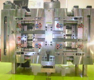
A”fit”refers to the mating of two segments. A leeway fit alludes to a mating where an ostensible freedom between the surfaces of the two segments. While a leeway fit furnishes for simple get together with insignificant inclusion powers, the freedom between the two segments allows the exact area of segments to stay obscure. Since tight resistances are needed in molds, impedance fits are normally used to find the mold segments.

Obstruction fits happen when the male segment has an ostensible measurement that is bigger than the ostensible element of the female segment, as demonstrated in injection moulding services for a center addition and a retainer plate. Since metals have a high versatile modulus, an inflexible obstruction fit can result when the distinction between the ostensible measurements is little, on the request for 0.01 % of the ostensible measurement. The snugness and inflexibility of the obstruction fit increments with the measure of impedance between the two segments. Sadly, the execution of obstruction fits is blocked by the dimensional varieties forced in the segments machining measures. Therefore, standard systems of fits have been created as far as possible on the elements of the segments.

The fits investigated here depend on a one-sided opening premise and have been changed over from U.S. standard units to metric units. Two of the most widely recognized principles for fitting include”Preferred Limits and Fits for Cylindrical Parts,” ANSI B4.1-1967 (R1999), and”Preferred Metric Limits and Fits” ANSI B4.2-1978 (R1999). ANSI B4.1 is investigated here because of its general straightforwardness and expansive materialness, however the mold originator may adjust to whatever standard is generally fitting. In this strategy, rectangular individuals with width, W, and length, L, are demonstrated as a roundabout part with clear distance across, D.

where C is a coefficient relating to the lower and furthest cutoff for the male or female segment given by worldwide norms. Table 12.1 gives coefficients to locational-obstruction fits (LN1 to LN3) and drive-impedance fits (FN1 to FN3). Locational-impedance fits are utilized when the exactness of area is basic and the parts require sidelong unbending nature. Be that as it may, locational-obstruction fits don’t give huge maintenance power in the stature course, so the parts should be gotten in the tallness heading to another segment through screws or different methods. FN1 to FN3 compare to drive fits with expanding impedance and requiring expanding addition powers. While drive fits give semi perpetual gatherings, mold plans for the most part give screws or different intends to decidedly holding the segments in the tallness heading.

This article is from https://www.injectionmouldchina.com/

Klarm Mould Offers Precision Molding Service

In the past model, the diversion of the side divider was not an issue. In any case, this issue would almost certainly be huge if the dissolve pressures were higher, the mold cavity was more profound, or the embellishment resistances were more tight. The mold creator from china mould produce services could increment the width of the cheek to decrease the side divider avoidance. In any case, this approach adds huge size and cost to the form. Another option is to use interlocks on the splitting plane close to the edges of the mold to move part of the bowing burden from the fixed portion of the mold to the moving portion of the mold.

Round and rectangular form interlocks are appeared in Fig. 12.20. The two sorts of interlocks ought to be put 0n the splitting plane and as near the form cavities as could be expected. When all is said in done, the rectangular interlock will give more noteworthy protection from diversion because of its bigger size and cross-sectional region across the interlock. However, round interlocks are accessible in more modest sizes and are simpler to introduce in a mold.

A detail perspective on a form configuration consolidating a round interlock is appeared in plastic precision injection mould factory. In this plan, the male interlock is found a way into a through opening in the B plate of the mold. The female interlock is found a way into a visually impaired pocket in the more profound A plate of the mold. The two interlocks firmly fit into the encompassing plates, and are held in the stature course with attachment head cap screws. It is significant that the mold deendorser doesn’t imperil the underlying respectability of the side divider by eliminating abundance mold material while joining the interlocks. At the point when the dissolve pressure is applied 0n the side divider, the interlock will move part of the heap from the A portion of the form to the B half of the mold. The utilization of the interlock adequately doubles the firmness of the side divider, bringing about a splitting of the measure of the side divider diversion.

Since bigger interlocks can convey higher burdens, the biggest interlock ought to be utilized that can be promptly consolidated into the mold plan. In the event that the interlock is presented to a sidelong power, Fateral, applied by the side divider, at that point the shear pressure in the between lock, Tinterlock, can be assessed as:

Tlnterlock= Flnteralock/Alnterlock

where Alnterlock is the cross-sectional region of the interlock at the splitting plane. In the event that the interlock is made of S7 device steel, the plan ought to give a shear pressure less than 300 MPa to stay away from disappointment. It ought to be noticed that temperature contrasts between the moving and fixed mold parts can cause misalignment of the between bolts and sped up wear during mold activity. Ordinary examination during mold support is suggested since this wear can lead straightforwardly to center movements and changes partially measurements.

Gauge the shear pressure in the 19 mm measurement interlock used to help the side mass of the cup cavity.

The essential vulnerability in this investigation is the assessment of the sidelong power applied to the interlock. This assessment of the sidelong power is confounded by the round state of the cup that gives a non-uniform cheek width between the guide pins. Be that as it may, a gauge can be given by accepting that the interlock is presented to the horizontal power from the close by surface of the mold pit. As demonstrated by the brought forth part of oem/odm industrial injection moulding design factory that represents the close by plastic, the powerful zone can be assessed as the item of the interlock width and the depression tallness.

Obviously, the interlock won’t be presented to the entirety of the horizontal power from the soften pressure applied as an afterthought mass of the mold cavity. A moderate gauge is that portion of the power will be conveyed by the interlock. This article is from www.injectionmouldchina.com

Different Vents

Openings for ejector pins are ordinarily bored and therefore reamed, In form producing, the diametral leeway between the ejector pin and ejector gap is normally 0.13 mm (0.005 in), which leaves 0.065 mm (0.0025 in) thickness on each side for venting. While this is fairly bigger than recently proposed vent thicknesses, this thicker leeway around the ejector pins is suggested for a few reasons. To start with, the leeway is valuable to dodge expanded sliding contact and ejector pin clasping. Second, ejector pins are typically machined through strong steel, so expanded glimmering because of separating plane diversion are impossible. Third, any observer lines related with glimmering at the ejector pins are typically situated on non-tasteful surfaces.

oem/odm industrial injection moulding design factory gives some run of the mill venting configuration subtleties utilizing ejector pins. Detail B shows an ejector edge and an ejec peak pin that have been doled out freedom, H, for venting. For both these ejectors, a venting channel has been given up to 3 mm away from the shape pit surface, after which the channel tightens to the ostensible bore of the ejector opening. Both of these components ought to be available in a decent ejector pin plan. The bigger channel serves to diminish the stream obstruction of the air while additionally aiding the get together of the ejector pins to the form. The shape is valuable to direct the top of the pin during mold get together.

The vent length, L, of 3 mm has been decided for illustrative purposes and is positively not obligatory. The past wind stream investigation with Eq. 8.2 infers that the standard leeway of 0.05 mm between an ejector pin and its opening will give huge wind current to venting. Therefore, it is conceivable to expand the length of the vent to an area that is helpful. For example, it might be alluring to stay away from an enormous vent channel close to cooling lines. As another model of plastic injection moulded components china, a form might be all the more monetarily delivered with a similar vent area through most of the center supplement, tightening to a bigger size just where the center addition faces the help plate.

For venting gas traps in dead pockets, one methodology is to utilize a form embed to vent. Mould manufacturers factory shows a plan wherein a rectangular pocket has been machined in the center supplement, into which a vented addition has been put. As appeared in Detail A, the vent just traverses the width of the rib where the caught air is normal. As appeared in Details B and C, the vent has thickness, H, of 0.05 mm and a length, L, of 2 mm. Thereafter, a more extensive vent channel has been set behind the vent. Since there is no ejector pin, there is no requirement for a smooth change between the vent and the vent channel.

It ought to be noticed that the venting capacity of the supplement gave in injection moulding services china might have additionally been given by utilizing an ejector edge at a similar area. The ejector sharp edge probably might have been given at lower cost while likewise encouraging the launch of the part. Accordingly, venting embeds are not particularly normal.

Another plan elective is the fuse of a sintered vent, envisioned in Fig.8.10, which is a kind of form embed that can be utilized for delivering gas in dead pockets. These gadgets are generally little in size, regularly going from 2 mm to 12 mm in distance across, and contain numerous little vent gaps in sizes going from 0.03 to 0.1 mm in breadth. Given their little size and non-machinable top surface, sintered vents are best positioned with their venting surface flush with level form cavity surfaces. Moreover, sintered vents can require discontinuous substitution or support as the miniature channels may stop up with no simple strategy for in-shape cleaning.

This article is from https://www.injectionmouldchina.com

Shear Rate

Simultaneous with deciding the gating location(s), the form originator from injection mould manufacturers in china should likewise decide the kind of gate(s$) to be planned. Frequently, the determination of a kind of entryway is evident once the gating areas are indicated. The essential factors that ought to be considered incorporate the sort of sprinter framework, the ideal strategy for de-gating, the permissible degree of shear rates through the entryway, and the subsequent stream that is wanted. To encourage entryway choice, Table 7.1 gives an outline of the sorts and properties of normal doors.

The de gating technique alludes to the utilization of the form activity to de entryway the parts, and doesn’t consider robotized de gating through mechanical technology. The expressed shear rate systems are inexact since they are a component of the entryway measurements and cycle conditions; the degrees of low, moderate, and high generally relate to shear rates on the request for 10, 40, and a 100,000 complementary seconds. At long last, most entryways bring about a spiral stream design out of the door with just the fan, glimmer, and stomach entryways deliberately intended to give straight liquefy stream into the form pit.

In choosing entryway areas and types, the utilization of blended hot and cold sprinters ought to likewise be thought of. Injection mold services china exhibits the utilization of a hot drop with a warm door that takes care of four sub-sprinters and parts masterminded in an outspread format. Such an arrangement could be utilized with a hot sprue bushing to spare material in an ordinary two-plate form, yet is very regular in the hot sprinter molds with an”X” complex setup. Such an application with the plan of Fig. 7.20 would bring about the creation of 16 holes with amazing material turnover in the hot sprinter, low weight drop from the trim machine, and productive material usage in the chilly sprinter.

The shear rates are determined by the recently given conditions to stream in strips and chambers. For reference, the formulae for Newtonian and force law streams are given in Table 7.2. These recipes depend on the volumetric stream rate as opposed to the direct dissolve speed. The explanation is that embellishment measures are arrangement with the volumetric stream rate being indicated, and that the straight dissolve speed of the polymer soften through the entryway isn’t promptly watched. Accordingly, shear rates in doors and sprinters are ordinarily determined as a component of volumetric stream rate.

High-quality double coler mold parts gives the material properties and suggested most extreme shear rates for certain materials. The greatest shear rates ought to be viewed as rough, best case scenario, since as a rule these qualities are taken from general rules for different materials. In all actuality, the greatest shear rates are reliant on the most extreme shear rate, yet additionally the whole warm and mechanical history of the polymer soften. In numerous if not most cases, a lot higher shear rates might be conceivable than the greatest shear rates recorded in Appendix A. Given this problem and the simplicity of expanding the size of entryways, it might be alluring for the shape planner to be”steel safe” and indicate a littler door with the expectation that the form will be tried and the door sizes expanded as important to keep away from inordinate shear rates and tweak the stream.

To ascertain the shear rates, the shape creator must determine some underlying door measurements. For thicker doors having low and moderate shear rates (counting the sprue, edge, tab, fan, and valve entryways), the underlying thickness might be set equivalent to the divider thickness of the embellishment at the location of the entryway. For more slender entryways having moderate and high shear rates (counting the pin-point, streak, stomach, passage, submarine, and warm doors), the underlying thickness might be set equivalent to one a large portion of the divider thickness of the embellishment. Strip-type doors likewise require the detail of the width. For blaze and stomach entryways, the width ought to be set to the edge length along which straight stream is wanted. For other strip-type entryways, the underlying width might be set to double the door thickness; this width can be expanded or diminished to modify the shear rates as vital.

This article is from https://www.injectionmouldchina.com.

Mold Material Selection

As a feature of the mold base plan and acquirement, the materials for the supplements and different segments should likewise be chosen by the mold manufacturer factory. Similarly as there are various plastics reasonable for injection shaping by plastic injection moulders china, there are numerous ferrous and nonferrous metals that are appropriate for use in injection molds.

A portion of the more normal materials and their properties are given. Of every one of these materials, AISI P20 remains the most well-known because of its inescapable commonality and good mix of properties. Nonetheless, P20 is once in a while inappropriately indicated in many embellishment applications since different metals would give better execution, lower form making cost, or lower infusion shaping expenses.

Over the most recent twenty years china mould design services, high-quality aluminum combinations have been embraced in many form structure applications while 3D printed polymers have been utilized for embeds yet with restricted life span.

Class 101 creation molds require the utilization of carbon/apparatus prepares, which are likewise favored for applications with moderate to high embellishment pressures. When the choice to utilize a steel has been made, the steel choice is regularly overwhelmed by concerns identified with wear and scraped area obstruction that is required for the mold’s utilization with fiber-filled tars. On the off chance that scraped spot opposition is definitely not a specific concern, at that point consumption obstruction likewise directs the material choice to a tempered steel, for example, SS420. Something else, instrument prepares, for example, P20 or S7, which are generally simple to machine and clean, are liked.

On the off chance that an embellishment application doesn’t present testing weight and wear prerequisites, at that point nonferrous metals are regularly thought of, particularly for short-run or moderate creation amounts. Airplane grade aluminum 7075-T6 and claim to fame grades created for molds, (for example, Alcoa QC10, Aleris Hokotol, and Vista Duramold) furnish high machining and embellishment efficiency with sensible quality. Product 6061-T6 is a lower-cost choice that gives fairly lower quality yet higher weldability and erosion opposition. For fast prototyping applications with extremely low creation amounts and lower forming pressures of high-precision molds made in china, polymer embeds delivered from a polyjet printing or melded affidavit displaying measure are possible. A portion of the significant properties and compromises of the different mold materials are examined straightaway.

Quality is regularly described by a definitive pressure that a material can suffer before disappointment, or by the yield pressure that can be applied to a material without causing changeless distortion. For infusion molds, nonetheless, neither of these properties ought to be used. Rather, the weariness quality (otherwise called as far as possible pressure) is the measure of pressure that can be consistently applied without causing disappointment.

One issue in basic plan is that the exhaustion conduct varies by material. For most prepares, the exhaustion quality is roughly one-portion of the yield pressure. In any case, aluminum and numerous different materials don’t have a continuance limit. Rather, these materials will inevitably come up short after constant cycling, paying little heed to how little pressure is applied. Therefore, the permissible pressure is characterized after a specific number of cycles (for instance, ten million). Sensible assessments of the admissible worry for weakness are given in Appendix B to various applicant materials; these qualities are later utilized for basic examination.

In light of the fact that mold creators and disintegrates look for changed material properties, there is nobody flawless form material. A typical compromise between the weariness quality and the warm conductivity is appeared in Fig. 4.26 for different materials. All in all, the materials that have the most elevated quality (A2, D2, H13, and P20) have the least warmth move. On the other hand, the materials with the most elevated warmth move (aluminum and copper amalgams, for example, C-18200) have the least quality. No material exists that has a high weariness limit pressure and a high warm diffusivity. P20, the most widely recognized of all mold materials, has great exhaustion quality yet low warm diffusivity, proposing that the form’s presentation might be improved by utilizing other form materials in some trim applications. This article is from www.injectionmouldchina.com.

Prototyping Cost Assessment in Mould Manufacturing

The prototyping cost assessment strategies were principally created for class 101 injection molds that are proposed by injection molding service china for large scale manufacturing of a great many shaped parts. In numerous applications, there is the need to create form tooling for lower creation volumes or to”bridge” model and creation. For some embellishment applications, the four normal assembling techniques are:

  1. Class 101 creation molds,
  2. Aluminum tooling for moderate volumes,
  3. Model molds made by added substance fabricating with photopolymers of direct metal laser sintering.
  4. Items straightforwardly made by 3D printing through intertwined statement demonstrating, laser sintering, or stereolithography. For every system, the forthright cost, peripheral expense, and absolute creation time as assessed can be a component of various objective creation volumes as an update to earlier work.

Cost assessment by injection mould manufacturers in china is a settled cycle where the genuine costs needed to secure a made item are completely accounted. The exactness of a quote will change dependent fair and square of detail taken in representing all the exercises and costs in assembling, just as the accuracy of the related occasions and expenses.

Once more, the standard structure for the all out creation cost, C, is applied for every one of the elective assembling procedures. The all out creation time can be likewise determined as where tinitial is the underlying lead time to get the initial segment, and tmarginal is the creation time for each extra part. The normal part cost may likewise be assessed .

Two critical issues in the assessment of shape prototyping techniques are (1) the nature of the secured parts and (2) the life span of the model tooling. To start with, model shape infrequently give the surface completion and execution of parts formed from creation tooling. Specifically, 3D printing measures have a limited goal or line width that can bring about unpleasant surfaces that limit the part style and execution. Straightforwardly created parts (by FDM, particular laser sintering, or stereolithography) have a diminished arrangement of evaluations just as fairly substandard properties identified with the trustworthiness of the established materials. Second, model tooling can have a shorter lifetime because of stress-related disappointments related with infusion of the polymer soften or potentially ejection of the shaped plastic parts.

Hence, it is critical to create sensible expense and time gauges for each assembling methodology by china high-precision mould suppliers. It gives some firm quotes to elective methodologies for creation of the shaped bezels. The initial two lines compare to the two-cavity hot sprinter and one cavity cold sprinter shape that were recently dissected. An option is the utilization of printed embeds that were delivered by a poly jet cycle with bright restored sap. This kind of shape embed has a lifetime on the request for 100 trim cycles, so the form embeds must be consistently recreated to accomplish high creation amounts, which prompts a generally high negligible creation cost of $33 and peripheral creation season of 1 h. Then again, the bezels might be legitimately delivered by melded testimony demonstrating or particular laser sintering with a minimal expense of $60 and a minor creation season of 4 h.

This article is from https://www.injectionmouldchina.com/.