Klarm Mould Offers Precision Molding Service

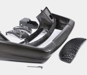
In the past model, the diversion of the side divider was not an issue. In any case, this issue would almost certainly be huge if the dissolve pressures were higher, the mold cavity was more profound, or the embellishment resistances were more tight. The mold creator from china mould produce services could increment the width of the cheek to decrease the side divider avoidance. In any case, this approach adds huge size and cost to the form. Another option is to use interlocks on the splitting plane close to the edges of the mold to move part of the bowing burden from the fixed portion of the mold to the moving portion of the mold.

Round and rectangular form interlocks are appeared in Fig. 12.20. The two sorts of interlocks ought to be put 0n the splitting plane and as near the form cavities as could be expected. When all is said in done, the rectangular interlock will give more noteworthy protection from diversion because of its bigger size and cross-sectional region across the interlock. However, round interlocks are accessible in more modest sizes and are simpler to introduce in a mold.

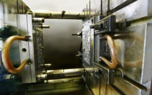
A detail perspective on a form configuration consolidating a round interlock is appeared in plastic precision injection mould factory. In this plan, the male interlock is found a way into a through opening in the B plate of the mold. The female interlock is found a way into a visually impaired pocket in the more profound A plate of the mold. The two interlocks firmly fit into the encompassing plates, and are held in the stature course with attachment head cap screws. It is significant that the mold deendorser doesn’t imperil the underlying respectability of the side divider by eliminating abundance mold material while joining the interlocks. At the point when the dissolve pressure is applied 0n the side divider, the interlock will move part of the heap from the A portion of the form to the B half of the mold. The utilization of the interlock adequately doubles the firmness of the side divider, bringing about a splitting of the measure of the side divider diversion.

Since bigger interlocks can convey higher burdens, the biggest interlock ought to be utilized that can be promptly consolidated into the mold plan. In the event that the interlock is presented to a sidelong power, Fateral, applied by the side divider, at that point the shear pressure in the between lock, Tinterlock, can be assessed as:

Tlnterlock= Flnteralock/Alnterlock

where Alnterlock is the cross-sectional region of the interlock at the splitting plane. In the event that the interlock is made of S7 device steel, the plan ought to give a shear pressure less than 300 MPa to stay away from disappointment. It ought to be noticed that temperature contrasts between the moving and fixed mold parts can cause misalignment of the between bolts and sped up wear during mold activity. Ordinary examination during mold support is suggested since this wear can lead straightforwardly to center movements and changes partially measurements.

Gauge the shear pressure in the 19 mm measurement interlock used to help the side mass of the cup cavity.

The essential vulnerability in this investigation is the assessment of the sidelong power applied to the interlock. This assessment of the sidelong power is confounded by the round state of the cup that gives a non-uniform cheek width between the guide pins. Be that as it may, a gauge can be given by accepting that the interlock is presented to the horizontal power from the close by surface of the mold pit. As demonstrated by the brought forth part of oem/odm industrial injection moulding design factory that represents the close by plastic, the powerful zone can be assessed as the item of the interlock width and the depression tallness.

Obviously, the interlock won’t be presented to the entirety of the horizontal power from the soften pressure applied as an afterthought mass of the mold cavity. A moderate gauge is that portion of the power will be conveyed by the interlock. This article is from www.injectionmouldchina.com

Final Shrinkage

The disastrous the truth is that to china mould manufacturing manufacturers, the specific shrinkage won’t be known before the shape is planned, manufactured, and tried. The objective in the setting up the last shrinkage proposal

■to give a shrinkage esteem that is near the real shrinkage of the material,

■to furnish a form machined with a shrinkage esteem that might be worked under a scope of cycle conditions to bring the part measurements inside particular, and

■to give a form that is machined”steel safe” with the end goal that the shape can be promptly adjusted if important to bring the part inside determinations.

The introduced shrinkage investigation should give sensible shrinkage gauges given legitimate dissolve temperatures and soften pressures. In any case of plastic injection moulded components china, the assessed contract age can differ broadly given vulnerability about material properties and handling conditions. Therefore, the shrinkage investigation ought to be considered as supplementing different wellsprings of data about shrinkage, The shrinkage examination ought not be utilized in disconnection given the potential for blunder. Notwithstanding, the shrinkage examination ought to be utilized to confirm the shrinkage gauges coming from different sources.

There are a few normal wellsprings of shrinkage information that might be utilized (notwithstanding examination) to help  plastic injection mold manufacturers china with setting up the last shrinkage proposal. Most ordinarily, a material provider or other testing research center may shape parts in a standard test form to assess the shrinkage. Commonly, the test form comprises of a 2 or 3 mm thick plaque that is shaped at mid-range dissolve temperatures and weights. The formed parts are then permitted to equilibrate for quite a while before their measurements are estimated and the straight shrinkage determined. This shrinkage data, when accessible, is generally precise since the testing was led for the specific material of interest at conditions near most embellishment applications. In any case, the gave shrinkage information may not be exact if the divider thickness or handling states of the embellishment application differ essentially from that of the test shape.

One critical issue with shrinkage information from a material provider is that the shrinkage information may not be founded on testing of the genuine material by high-precision molds made in china, but instead suppositions that the material will carry on as evidently comparative materials that have been recently tried. A more costly however more precise option is to configuration, assemble, and test a model shape that has a stream length, divider thickness, and cooling framework like the particular embellishment application. Such model embellishment gives dissolve weights and temperatures that ought to be fundamentally the same as those of the last creation form, so the shrinkage saw with the model shape should be near the last production form. While the advancement of a model shape can be costly, the exactness of the shrinkage estimations can be helpful in close resilience applications.

Another choice is to depend on shrinkage information from past form plans and decay insight. Much of the time, molds may as of now have been planned and worked for creation of moldings that are fundamentally the same as the current form plan application. In such cases, the mold originator of injection molding service china may acquire the best gauges by contrasting the estimations of the moldings and those of the shape steel measurements.

Before making last proposals, in any case, the shape originator ought to ask with the decay to check if the disintegrate would have liked to work the trim machine at various liquefy temperatures as well as weights. Provided that this is true, the form originator ought to ask the disintegrate to create moldings at the favored conditions (regardless of whether the moldings fall outside of determination), and afterward ascertain the shrinkage of these moldings for use in shape plan applications.

A fourth choice is to perform modern PC reenactment of the mold filling, pressing, and cooling stages to foresee the straight shrinkage in the trim application. While PC reproduction uses further developed material science and gives more definite outcomes than the shrinkage examination introduced here, the PC reenactment is as yet dependent upon similar mistakes with respect to the expected material conduct and preparing conditions. Nonetheless, the mathematical recreation can be important to approve the manual shrinkage examination while giving nonuniform shrinkage gauges over the shape pit.

In building up the last shrinkage suggestion, the form architect ought to play out the introduced shrinkage investigation and affirm the outcomes with information from the material provider and past experience, if accessible. On the off chance that the shrinkage rate is dubious, at that point the shape fashioner ought to discuss the expected blunder with the disintegrate, material provider, and end-client to diminish the vulnerability and survey obligation should the used shrinkage rates be so incorrect to bring about expensive form changes. In certain agreements, the last shrinkage proposal is the duty of the form’s client who eventually pays for the expense of the shape plan and any slip-ups. In different cases, no gathering might be happy to acknowledge duty regarding a questionable shrinkage rate, so the gatherings may concur that a model embellishment venture is important to portray the shrinkage and diminish hazard.

This article is from https://www.injectionmouldchina.com

Tunnel

Except for the pin-point entryway utilized with a three-plate mold, all the first gates designs from china mould design services require the expulsion of the feed system from the trim by some post-forming framework (as a rule the administrator). The passage entryway is a typical kind of gate that can be viewed as a variation of the pin-point door. Its essential bit of leeway is that the passage entryway pr0vides for programmed de-gating with the activation of a basic two-plate shape. The plan of a passage entryway for the cover shaping is appeared. Contrasted with the pin point entryway, the progressions have all the earmarks of being corrective with the expansion of certain turns and tightens. These distinctions are irrelevant as for the progression of the plastic dissolve, so the components of the passage entryway ought to be resolved as recently examined to accommodate sensible shear rates and weight drops.

From the outset, the passage gate appears to be fundamentally the same as the pin-point entryway. Nonetheless, they vary altogether in structure and capacity. The capacity of the passage gate can be perceived by looking at the form plan. A cross area through the shut shape with the passage entryway is appeared. The way in to the capacity of the passage entryway is that the passage gate”tunnels” through the pit embed. The embellishment will move away from the depression supplement and remain on the center with the passage door when the shape opens. Simultaneously, the kickoff of the mold powers the passage part of the runner to incidentally stay with the cavity embed. The movement of the center supplement away from the hole embed causes the passage gate to break at its intersection with the embellishment. The embellishment and the feed system would then be able to be launched out as in an ordinary infusion forming measure.

The breadth of the passage entryway at the hole ought to be intended to stay away from unreasonable shear rates and weight drops. For the passage entryway to work dependably, there are two significant points that must be indicated. Initial, an ostensible 45 degree point ought to be kept up between the centerline of the passage door and the splitting plane to take into consideration the transmission of shearing worries to the entryway. Second, the passage door ought to have an included shape point of 20 degrees t0 guarantee that the passage entryway doesn’t stick in the form and that the passage entryway breaks at the intersection with the trim. To guarantee satisfactory auxiliary respectability of the pit undercut, the passage gate ought to be situated in any event three passage measurements off the splitting plane.

The passage gate is a sharp plan since it accommodates programmed de gating without huge venture. The essential danger in application is that the passage entryway might be inappropriately planned or wear with the end goal that lhe runner system doesn’t dependably degate from the trim. T0 help the de-gating of the passage gate from the formed part, the runners ought to be planned with close by sucker pins, to hold the runner system on the center side. In the event that the passage entryways and the runner system stay on the hole side, at that point they can’t be taken out through activation of the discharge system.

There are a few varieties of the passage entryway for the high-precision molds made in china. Similarly as the passage entryway burtows up into the hole embed, the term”submarine”gate alludes to a plan variation where the passage door slides into the center supplements. The activation of the ejector system and the launch of the embellishment of the center at that point demonstration to break the entryway and strip the feed system from the trim. With both passage and submarine entryways, it is likewise conceivable to configuration expanded gates that bend around vertical side dividers to gate onto the inside surfaces of the part. Such an all-inclusive submarine door configuration, otherwise called a”banana”or”cashew”gate,, however such plans represent extra danger as for solid de-gating.

This article is from https://www.injectionmouldchina.com