Volumetric Shrinkage

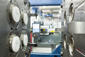
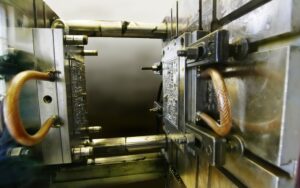
As the polymer melt fills, packs, and cools in the form hole, it will be exposed to a scope of liquefy weights and temperatures. Simultaneously, the particular volume of the polymer melt in the cavity will change as needs be. oem/odm 2 shot injection moulding factory gives the melt’s weight, temperature, and explicit volume history during a trim cycle.

china mould design services demonstrates that during plastication, the soften’s temperature and explicit volume increments. During filling, the soften temperature is almost consistent, however an expanded liquefy pressure causes a decrease in the particular volume. During pressing, the material cools with a decrease in weight and temperature, causing a further decrease in the particular volume. After the finish of the pressing stage, no extra material is constrained into the form hole, The melt cools and therapists, causing the soften strain to rot. When the soften pressure arrives at air pressure, the plastic can pull away from the shape divider, with additional volumetric shrinkage making malleable burdens create in the formed part. Toward the finish of the cooling stage, the form opens and any lingering melt pressure is delivered. The part is then shot out and permitted to cool to room temperature.

The particular volume of the plastic after every one of the different embellishment stages is spoken to by china mould manufacturing manufacturers with a scale multiple times the qualities diagramed in plastic injection mold manufacturers china. Each solid shape contains the soften temperature and weight toward the finish of various trim stages, while the size of each 3D square speaks to the particular volume of the melt.

Plastic prototype mould china show that the particular volume subsequent to cooling is 0.97, and the particular volume after launch (when the part has cooled to room temperature) is 0.955. In that capacity, the adjustment in the particular volume of the plastic is – 0.015. This adjustment in the particular volume will lead legitimately to straight shrinkage in the components of the shaped plastic part. The assessment of the volumetric shrinkage toward the finish of the pressing stage is significant to the computation of the volumetric and direct shrinkage.

A sensibly precise gauge of the volumetric shrinkage can be determined if the melt weight and temperature toward the finish of the pressing stage are known. As recently talked about, the soften pressure in the cavity during pressing was assessed as 66 MPa. The temperature of the plastic in the depression is a component of the material properties, form calculation, and handling conditions. In the event that the pressing time is known, at that point the normal liquefy temperature can be assessed as talked about in Chapter 9. Notwithstanding, a more basic methodology is to expect that the soften temperature toward the finish of the pressing stage is equivalent to the no-stream liquefy temperature, which is the temperature at which the polymer has a high consistency. The no-stream temperatures for an assortment of materials are given in Appendix A.

The adjustment in the particular volume can be determined as the adjustment in the particular volume of the plastic toward the finish of the pressing stage and the particular volume of the plastic during end utilization of the shaped part.

Since the no-stream temperature of 405 K is over the change temperature of 386 K,the coefficients for the soften state ought to be utilized. The particular volume toward the finish of the pressing stage (66 MPa and 405 K) can be determined.

This article is from https://www.injectionmouldchina.com

Shrinkage

Plastic part originators regularly use plan for assembling and get together (DFMA) rules to lessen the quantity of parts in a gathering for injection mold manufacturing china. Hence, plastic part plans can be incredibly perplexing with numerous highlights and tight resistances.

The conveyance of plastic moldings that fulfill the dimensional prerequisites is a joint duty of the form architect, disintegrate, material provider, and part planner. The part planner ought to furnish a plan with uniform thicknesses and reachable determinations. The material provider ought to give steady polymer tar and helpful direction with respect to material properties. The disintegrate should choose reasonable and reliable handling conditions for activity of the shape. The form planner ought to furnish a shape with adjusted liquefy filling and cooling, and for which the form cavity measurements were designed for a suitable shrinkage.

The shrinkage of shaped plastic parts is administered essentially by the warm withdrawal of the plastic, the compressibility of the plastic at pressing weights, and less significantly by the warm development of the form metal. The grouping of steps that decides the last part measurements is appeared in double coler mold parts manufacturers. Preceding embellishment, the form cavity measurements may change somewhat from the machined measurements given that the shape might be at a coolant temperature over the room temperature. The warm extension of the shape cavity, shown by the ran lines in mold manufacturer factory, can be assessed as the shape metal’s coefficient of warm extension increased by the temperature contrast between the form coolant and room temperature. For a P20 form embed, the coefficient of warm extension is 12.8. 10-6 m/m°C. In the case of embellishment ABS, the shape working temperatures may be 60°C, which is 40°C above room temperature. In that capacity, warm extension of the form pit is assessed as 0.0005 m/m or 0.05%(12.8.10-6 m/m°C times 40°C).

While this adjustment in form measurements is little contrasted with the greatness of shrinkage of the plastic, it is promptly anticipated and ought to be viewed as while indicating the last shape pit measurements for tight resistance applications.

During the filling and pressing phases of the trim cycle, the dissolve in the shape cavity is compelled by the surfaces of the form pit and packed at high weights. These high weights cause stresses, σ, that would make the liquefy in the shape depression grow if not contained by the form hole. During in-shape cooling, the temperature of the dissolve drops. In most trim cycles, the warm constriction of the dissolve causes the rot of the liquefy weight and arrival of related compressive anxieties. Ensuing cooling of the soften causes critical warm constriction. The trim will truly contract in the shape through the thickness and along any unconstrained surfaces, for example, ribs and side dividers. In certain zones of the part, nonetheless, the shrinkage of the plastic is obliged by side dividers. In these regions, the plastic doesn’t recoil so all things being equal creates interior tractable remaining anxieties.

Upon launch, a significant part of the formed in stresses are delivered, and the plastic embellishment promptly shrivels when it is pushed off the shape center. Further post form cooling permits the embellishment to equilibrate at room temperature and extra unwinding of any remaining pressure. In the model appeared in china precision plastic injection mold factory, the complete change long, AL, was – 0.005 m/m. This general decrease of the part length, Lmolding, from the planned shape depression measurement, Lcawity, is alluded to as the shrinkages.

The adjustment long of the embellishment because of shrinkage during the trim cycle is huge in most embellishment applications, and ought to be represented during the shape configuration measure. The capacity of a disintegrate to give tight resiliences is firmly identified with the shrinkage during embellishment [3]. Resistances on plastic part measurements are commonly determined as a level of their ostensible length. For example, the Society of the Plastics Industry gives rules about norm and tight resistances in business creation [4]. A commonplace resilience might be indicated as 土0.4% while an average tight resistance may be + 0.1%. In either case, a 0.5% shrinkage rate will make the embellishment be out of resilience. All things considered, the shape fashioner must consider the plastic shrinkage while indicating the form cavity measurements. In the event that the shape fashioner realized that the net shrinkage was 0.5 %, at that point the form pit measurement would be set to 100.5 mm to create a trim 100 mm long.

This article is from https://www.injectionmouldchina.com

Condition Heating

Given the huge warm mass of the mold and the cooling framework, another procedure for injection moulding services china to control the shape divider is to utilize conduction radiators at or close to the outside of the shape. One plan is appeared in high-quality double coler mold parts; this was created to give a smooth surface completion aside of a frothed plastic item. The shape comprises of a hole embed 12 and a center addition 10, both including an organization of cooling lines 34 and 36 according to regular form plan. A slight metallic sheet 38 adjusts to the outside of the form pit 12, with a flimsy protecting layer of oxide kept between the sheet and the cavity embed. The meager metallic sheet 38 incorporates an initial 40 to convey the plastic liquefy from the sprue 32 to the shape hole 14. Electrical link connections 46 and 48 join the sheet 38 to low voltage, high flow electric links 50 and 52.

Only preceding mold conclusion, the switch 54 is shut to pass a high current through the sheet 38. In this plan, a 0.2 cm thick steel plate was utilized with a length and width of 30 cm and 10 cm, separately. To investigate the warming prerequisites, consider a commonplace formed part with a warmth limit of 2000 J/kg°C, a 3 mm thickness, a liquefy temperature of 240°C, a launch temperature of 100°C, and a process duration of 30 s. For this situation, the warmth load forced on the form by the ABS liquefy is 28 kW/m2; given that the cooling lines are put on different sides of the shape, the cooling power is around 1.4 W/cm2. Accordingly, a 30 cm by 10 cm warming plate must convey in any event 420 W basically to beat the warmth move to the cooling lines before the temperature of the warming plate starts to increment essentially.

It is noticed for china industrial injection mold manufacturers that conduction radiators are broadly accessible with power densities surpassing 250 W/cm2. Such a radiator, whenever set on the outside of a shape pit, could expand a 0.2 cm by 30cm by 10 cm steel plate’s surface temperature by 200°C in 6 s, Attempts have been made to fuse higher force, slim movie warmers straightforwardly into the mold surface. Notwithstanding, such endeavors to consolidate conduction radiators into molds have not been generally fruitful for in any event three reasons. To begin with, the huge, cyclic weight forced on the heater(s) by the polymer dissolve will in general exhaustion the radiators. Second, it is hard to design the heater(s), form cavity, and cooling channels to give the uniform divider temperature needed to convey tasteful surfaces with tight dimensional controls. Third, the radiators are situated between the shape depression and the cooling channels, will in general lessen the pace of warmth move during cooling, thus expand the cooling time. Gauge the energy needed to warm the form center and cavity embeds portrayed in pom moulding parts manufacturers china for a beat cooling measure. To gauge warm energy, the center and depression supplements can be displayed all together of steel with a width and length of 100 mm and a profundity of 200 mm. Given a thickness of steel of 8000 kg/m3, the mass of the additions assessed as 16 kg.

This article is from www.injectionmouldchina.com

Bubbler

Bubblers are a somewhat more modest option in contrast to perplexes with fundamentally the same as cooling execution. In this plan, appeared in precision molds factory, the coolant circles around the outside of the bubbler, and returns down within the bubbler. Contrasted with an astound, the bubbler doesn’t contact the center thus conveys no heap from the center pressure. Along these lines, the bubbler is planned with an extremely flimsy divider thickness and minimal measurements. Bubblers with a distance across of under 2 mm can be utilized by china plastic pipe fitting mould maker in bored openings under 3 mm in measurement. The essential disservice of bubblers is that they require two cooling channels- – one to give stream around the bubbler and one moment to restore the stream from inside the bubbler. Thusly, the advantage of the more modest opening measurement related with the bubbler accompanies a to some degree more prominent cost concerning its establishment.

A warmth pipe is a shut gadget with an inward hole that contains a liquid which bubbles at a temperature between the soften temperature and the coolant temperature. Hairlike activity makes the cooled inside liquid ascension the external dividers of the warmth pipe. At the point when set inside a form center as appeared in mould produce manufacturers, the expanded temperature along the length of the warmth pipe causes the liquid inside the warmth line to dissipate and re-visitation of the base of the warmth pipe where the gas cools and gathers. Due to this constant pattern of buildup and vanishing of the fluid inside the warmth pipe, moderately high cooling rates can be accomplished without requiring the progression of shape coolant along the pivot of the form center.

The warmth pipe has become a standard shape segment that is accessible from various providers. Their essential favorable circumstances incorporate little size, great warmth move rates, and simplicity of establishment. In any case, their cooling viability isn’t as high as that as bubblers or bewilders. The explanation is that the mass movement of the form coolant, which has a high explicit warmth and a much lower temperature than the soften temperature, gives an a lot higher pace of warmth move than that gave by heat pipes. Warmth pipes additionally have potential issues identified with their underlying reaction (since they require a huge temperature slope to start a compelling buildup vanishing cycle) just as their adequacy under an assortment of coolant and soften temperatures (identified with the math and material properties). For centers with little distances across, under 5 mm, it may not be conceivable to convect heat along the pivot of the center utilizing any of the recently referenced plans.

Accordingly, the main choice might be to use a conductive pin to encourage heat move as appeared in china high precision mold manufacturer. In this plan, form coolant streams around the rear of the pin to move however much warmth as could reasonably be expected from the pin. With high length to breadth proportions, be that as it may, the warmth move isn’t powerful. In such cases, the center pins forestall the progression of warmth down the length of the center pins and act fundamentally as encasings.

This article is from https://www.injectionmouldchina.com

Induction Heating

Induction heating is another way to deal with expanding the mold divider temperature before shape flling, and is seeing expanded application for micromolding, gleam, and quality. One plan is appeared in mould manufacturers china; this was created to infusion mold fortified thermoplastic composites with prevalent surface gleam and considerably no surface demoldities. T0 lessen energy utilization and warming time and high precision plastic injection mould price, just a little segment of the shape’s surface is specifically warmed by high-recurrence enlistment warming. As appeared in Fig. 9.30, a regular infusion molding machine 3 conveys polymer soften to a shape comprising of a fixed mold half 4 and a versatile shape half 5.

Preceding mold conclusion and flling, a high-recurrence oscillator 1 drives substituting current through an inductance curl (inductor) 2 briefly positioned close the surface(s) of the mold. At the point when a high-recurrence rotating current is gone through the inductor 2, an electromagnetic field is created around the inductor, which along these lines produces swirl flows inside the metal. The obstruction of the shape metal along these lines prompts interior Joule warming of the mold surface. Follows An and B in high precision mould china exhibit the expanded shape surface temperature at areas An and B brought about by induction heating; follows C and D show no underlying impact at area C and D away from the enlistment warming however later increment with the warmth move from the infused polymer soften into the mold pit.

Similarly as with all the recently portrayed methodologies for shape divider temperature control, decays wish to raise the surface temperature of the mold as fast as could reasonably be expected. The warming force through a high recurrence induction heating is relative to the square of the substituting recurrence, the square of the current, and the square of the curl thickness, among different components like china inner part mould manufacturers. In that capacity, the inductors must be painstakingly intended to locally warm the shape surface in a controlled way to keep away from an unwanted temperature circulation. For instance, an inductor was produced using copper container of 5 mm distance across and twisted as a winding with a pitch of 5 mm. The separation between the outside of the metal shape and the inductor was set to 1 cm. Analyses demonstrated that a driving recurrence of 400 kHz yielded a warming force at the mold surface on the request for 1000 W/cm2, which required roughly 10s to expand the outside of the shape by 50°C.

Contrasted with beat cooling and conduction warming, enlistment warming accommodates expanded warming rates with little included shape unpredictability. The essential issue in usage is the plan of the inductor, and specifically the dividing of its curl windings and their connection to the mold surfaces. In the event that the plan is ill-advised, at that point the warming might be restricted to low power levels. Tests showed that a warming force under 100 W/cm2 didn’t altogether build the shape surface temperature and in the long run made the over-burden breaker incite. Then again, when the force yield surpassed 10,000 W/cm2, the pace of the surface temperature increment turned out to be too steep to even consider controlling with the end goal that uniform warming was not, at this point potential; imperfections, for example, gleam abnormalities, sink marks, and so forth were seen with temperature contrasts of more than 50°C over the outside of the mold.

This article is from https://www.injectionmouldchina.com

Interlocking Core

At the point when the part math permits, slim centers with little breadths can be interlocked with the contradicting mold cavity as appeared in Fig. 9.25. Such a plan from injection moulding design china has two preferences. In the first place, the interlocking of the center with the depression offers help for the center and will in general decrease the center flexture as broke down in oem/odm industrial injection mold factory. Second, the interlocking gives a methods by which to pass on coolant from the moving side of the shape, through the center, and to the fixed side of the form. Air is ordinarily utilized as the coolant in such a plan since this coolant will be presented to the shaped part and the climate when the form is opened. While air has a low thickness, which lessens its cooling viability, plan with air channels will give considerably more warmth move than a strong center pin.

There are two regular embellishment circumstances in which there is irrelevant warmth stream from one side of the trim. The first is the long slim center indicated before in china injection mold factory, which depends exclusively on conduction down the hub of the slim pin to move heat from within the embellishment. Since the pin is so thin, there will be very lttle heat move down the length of the pin. Thus, most of the warmth must be moved to the cooling lines in the depression embed.

pom moulding parts made in china plots the warmth motion in a form having a thin center pin. The transition vectors demonstrate that there is some noteworthy warmth move around the centerline of the pin towards the coolant at its base. Nonetheless, the pin’s cross-sectional zone is little to the point that there is an overwhelming outspread warmth motion at the outside of the pin. All in all, the hot plastic liquefy that is contacting the center must exchange a large portion of its warmth entirely through the plastic to the metal and cooling lines of the depression embeds.

As to the cooling of such slim centers, the form creator ought to comprehend that the cooling time will probably be stretched out because of the restricted warmth move to the coolant. A most dire outcome imaginable can be promptly examined by expecting that there is no warmth ransfer deeply. The warmth fIux in this situation is appeared in china high precision mold manufacturer. Since all the warmth must exchange through one side of the trim, the warm conduct is basically equivalent to if two layers of the plastic dissolve were on head of one another. This twofold thickness portrayal is legitimate since the temperature circulation is symmetric over the centerline so there is no related warmth motion.

Uneven warmth stream will likewise happen when forming a plastic layer on head of another material that is ineffectively conductive, as in two-shot (multishot) shaping or overmolding, In these cycles, the primary layer or item may go about as a cover that restricts the warmth stream from the polymer liquefy just injected. As in china mold component machining, the impact of the protecting layer is to confine the warmth stream to only one side of the polymer liquefy. To ascertain the warmth move rates for such uneven warmth streams, mold manufacturing factory might be utilized by subbing double the genuine thickness of the embellishment for the thickness variable, h. The net outcome is that any trim application with an uneven warmth stream will have roughly a four-overlap increment in the cooling time over an embellishment cooled from different sides.

This article is from https://www.injectionmouldchina.com

Cooling

As an option in contrast to penetrating cooling lines, cooling lines that adjust to the state of the shape hole can be processed into the back essences of the pit or center embeds as appeared in oem/odm industrial mold factory. For this situation, a ball end factory is directed around the lower part of the center addition, after which interfacing lines are bored aside of the shape. The cooling lines can consequently intently follow the shapes of the formed part, in any event, for bended surfaces. The area of the coolant passageway and ways out has been chosen to adjust the weight drop between the interior and outside circuits.

Despite the fact that the cooling embed configuration appeared in injection tooling factory gives uncommon cooling, it presents potential spillage issues. In this plan, a notch has been furnished and fitted with a gasket. At the point when attached firmly to the help plate, the gasket will forestall spillage outside the form. In any case, spillage ought not out of the ordinary at any ejector pins found inside to the territory encompassed by gasket. In this application, a stripper plate could be effectively utilized as examined in stainless steel metal injection moulding housing manufacturers china.

Assembling innovation is proceeding to progress, and generally new shape causing advances to incorporate polyjet [17], stereolithography [18], intertwined testimony displaying (FDM, [19]), and specific laser sintering (SLS, [20]) as immediate metal laser sintering (DMLS, [21]). These 3D printing advances give the capacity to straightforwardly put cooling lines at any area as the center and cavity embeds are being printed. Returning now to the center addition for the cup, a conformal cooling line configuration is given in Fig. 9.17 in which the coolant is directed to the focal point of the supplement and afterward branches to a progression of veins like an inside drinking fountain, in this manner disposing of the temperature slopes appeared in high precision molds china.

Since almost any math can be made with these 3D printing advancements, inside cooling lines of subjective plan can be made to adjust to the cavity surfaces to improve heat move rates and consistency. Huge continuous issues incorporate quality, porosity, and surface completion of the printed embeds. In particular, polymer shape embeds made by polyjet, stereolithography, FDM, and SLS give an ease way to deal with model forms yet have low warm conductivity and quality.

The plan of two shots mould made in china would at present require an all-inclusive process duration contrasted with metal supplements, on the request for 100 s, while being probably not going to endure in excess of a couple dozen trim cycles. Setting the cooling lines further from the form surface would lessen the quality issues, yet refute the advantage of having conformal cooling lines. On the other hand, DMLS additions would give adequate quality as proposed by the survey of material properties depicted by Kruth et al. [20]. Be that as it may, such DMLS supplements would be very costly while not giving adequate surface appearance.

Another way to deal with diminishing temperature angles is to use profoundly conductive addition materials, for example, Cu 940 or Aluminum QC10, for divides or the whole center supplement. Since these materials have a lot higher warm conductivity than steel, their specific use in molds having”hot spots” will in general diminish the temperature variety over the depression. For instance, the anticipated temperature appropriations toward the finish of the trim cycle for the cup center addition utilizing a Cu 940 material are given in Fig. 9.18. Similarly as with the outcomes accommodated a steel center in Fig. 9.11, each mold line speaks to a 2°C change in temperature. The outcomes demonstrate that the temperature inclination has been diminished by around 60% contrasted with the temperature angles appeared in factory injection mould.


Conductive additions can likewise give improved cooling in the interior corners of moldings. Due to the warmth move in three measurements and constraints with respect to the vicinity of the cooling line to the form divider, the cavity embed for will in general direct considerably more warmth away from the shaped plastic contrasted with the center supplement. The temperature dissemination for a normal plan utilizing a solitary material for both the center and the hole is appeared in Fig. 9.19(a). At the point when the center and pit embeds both comprise of P20, there is a 5°C temperature angle over the divider thickness of the trim. Notwithstanding, onlya 1 °C differential over the divider thickness of the trim happens when the center supplement is determined with Cu 940 as appeared in Fig. 9.19(b).The essential favorable position of exceptionally conductive center supplements is the capacity to deliberately control the warmth stream. While these materials increment the pace of warmth move, their properties are not suitable for use all through the shape. There are two essential reasons. To start with, it ought to be noticed that the improved temperature circulations accomplished in Fig. 9.19(b) were the consequence of utilizing various materials for the center and depression embeds. These temperature conveyances would not have been as uniform if both the center and hole embeds were produced using Cu 940. Second, these profoundly conductive materials will in general have lower hardness and are more powerless to wear. Thusly, exceptionally conductive additions might be best when utilized in applications with high creation volumes, low to direct infusion pressures, and non-rough materials.

This article is from https://www.injectionmouldchina.com

Cooling Line Pitch

When the cooling line profundity is chosen, the separation between the cooling lines (known as the”pitch”) is appointed. A more tight pitch, Wine, between cooling lines accommodates quicker and more uniform cooling. Nonetheless, a more tight pitch likewise implies all the more cooling lines and the probability of contentions emerging between the cooling lines and other shape segments. The mold architect from injection mould manufacturers should choose a cooling line pitch that is fitting for the spec ific shaping application utilizing examination.

The temperature expectation of the liquefy during cooling includes the arrangement of an arrangement of illustrative differential conditions. While this is promptly comprehended utilizing the limited component strategy as over, no reasonable systematic treatment has yet been created. This capacity is plotted in newest double coler mold parts for steel and an aluminum form materials. The examination shows that the variety in the warmth transition is under 5% up to a cooling line pitch equivalent to double the cooling line profundity. Thereafter, the variety in heat motion increments significantly and is characteristic of more slow paces of shape cooling and high temperature angles inside the formed part.

To stay away from a critical temperature angle between cooling lines, it is suggested that form planners utilize a cooling line contribute the scope of relying upon the necessities of the application. An item with free resiliences would probably approve of a cooling line pitch equivalent to a few times the cooling line profundity. For more tight resistance applications or for applications requiring quicker process durations or more uniform cooling, a closer separating equivalent to the cooling line profundity is alluring.

Figure 9.5 shows that the utilization of profoundly conductive materials, (for example, aluminum or copper) really expands the variety in heat motion by improving the warmth conduction between the cooling line and the cavity surface. All things considered, the utilization of profoundly conductive materials doesn’t legitimately take into consideration a more extensive pitch and a diminished number of cooling lines. On the off chance that less cooling lines are wanted, at that point this may best be cultivated by choosing a huge cooling line profundity and as yet setting the pitch to twice this sum. Exceptionally conductive form materials would then be able to be used to achieve high paces of warmth move with uniform cooling.

Transient warm recreation was performed for the cup/cover family shape for two form plans having diverse pitch to cooling line profundity proportions. China standard components for injection mold plots the warmth stream from the centerline of the embellishment in the pit to the cooling. In the figure, the lengths of the bolts speak to the overall measure of warmth streaming out of the form depression at that area. As the cooling lines are moved further separated two unfavorable conditions emerge. To start with, the compelling warmth move rate at the form divider is diminished given the limited limit of the cooling lines to eliminate heat. Second, a critical variety in the warmth move rate emerges over the cavity surface.

This variety in the warmth move rate over the hole surface will offer ascent to a slope in the temperature of the moldings at the hour of launch as plotted in oem/odm automatives injection molding design factory. With a tight cooling line pitch, the moldings are catapulted not just with a lesser temperature variety over the trim, yet in addition at an essentially lower temperature. With a wide pitch, the moldings display an a lot higher temperature inclination and an a lot higher temperature.  Curiously, expanding the process duration for the form with the more extensive pitch doesn’t decrease the temperature angles without fundamentally expanding the cooling time to permit the whole shaped part to move toward the coolant temperature.

This article is from https://www.injectionmouldchina.com

Coolant Flow Rate

When the cooling time is known to the china injection mold maker, the warmth move rate or”cooling power” expected of the feed system of the double coler mold parts can be determined. The aggregate sum of warmth to be eliminated by the cooling framework, Q mlingsg, is:

where mmoldings is the com bined mass of the formed parts and any related cold sprinters, which can be assessed as the volume of these moldings times their thickness at room temperature.

The cooling power is the characterized as the measure of energy that the must be eliminated every second of cooling time:

Normally, an injection mold has numerous cooling lines. Expecting that the mold is all around planned and each cooling line renoves a similar measure of warmth, at that point the warmth move rate per cooling line might be assessed as:

where nuines is the all out number of cooling lines in the shape. Now, the oem/odm largest plastic injection molding companies ought to perceive that various plan cycles might be important to play out the cooling investigation for various cooling line formats with shifting number of cooling lines.

Any warmth eliminated from the polymer dissolve in the shape hole must be diverted by the coolant. In that capacity, the coolant will increment in temperature as it goes through the shape. This temperature increment isn’t alluring, since the coolant will give less cooling to the last segment of the form through which it streams, If the coolant temperature increment is excessively incredible, at that point warm slopes will emerge over the shaped part, which may prompt differential shrinkage and warpage.

Given a volumetric stream pace of the coolant, V2o the expansion in the coolant

coolant’ temperature along one cooling line is:

The warm properties of some normal coolants are given by plastic mould manufacturers factory. The necessary coolant stream rate can be determined given the permissible increment in the coolant temperature. A commonplace permissible increment in the coolant temperature is 1°C. For an exactness forming application, the permissible increment in the coolant temperature might be 0.1°C. A lot more tight control of the coolant temperature requires a lot higher stream rates, but gives little included advantage given that the form hole surface temperatures will in general change all the more fundamentally between the cooling lines as later talked about.

Subsequent to assessing the necessary coolant stream rate, the plausibility of this worth ought to be checked against the abilities of business form temperature regulators. The determination for an ordinary coolant temperature regulator and an oil temperature regulator are recorded in oem/odm medical mold design factory.

The admissible scope of cooling line distances across would now be able to be resolved dependent on the warmth move and liquid stream limitations. To guarantee satisfactory warmth move from the shape steel to the coolant, tempestuous stream in the coolant is wanted. In the event that the cooling line width is excessively enormous, at that point the direct speed of the water may not be adequate to guarantee violent stream. To guarantee violent stream, the Reynolds number, Re, ought to be more prominent than 4000.

An additionally restricting imperative administers the base cooling line breadth, which is identified with the weight drop needed to compel the coolant through the cooling lines at the necessary volumetric stream rate, The weight drop for water through a cooling line can be assessed from pipe stream.

To figure the base cooling line measurement, the line length and passable weight drop over the cooling line must be known. This data can really be somewhat questionable, since it depends not just upon the design of the cooling lines in the shape, yet additionally whether the cooling lines are funneled in arrangement or equal.

This article is from https://www.injectionmouldchina.com

Cooling Time Estimation

The cooling time is characterized as the measure of time required after the mold is filled for the plastic to turn out to be adequately unbending to launch. The accompanying hypothesis is given to help the assessment of the hypothetical least cooling time for the mould manufacturers factory. By and by, cooling times can be significantly longer than those anticipated by examination for two reasons. To start with, the accompanying examination accepts flawless warmth conduction between the plastic and the form, while there is known to be a considerable warm contact obstruction between two unique materials. The cooling time can be additionally expanded during injection moulding services china by slim holes, which open up between the contracted trim and the form dividers. Second, the cooling time is regularly not driven by the inflexibility of the part, yet rather by quality prerequisites that may require the decay to stretch out the cooling time to accomplish the particulars.

Since there is next to no volumetric dissolve stream of the liquefy after the form filling stage, there is almost no warmth convection. Thus, the exchange of warmth between the plastic and the form is administered by the transient warmth conduction condition:

Here, T is the temperature, t is the time, 2 is the measurement in the thickness bearing, k is the warm conductivity, ρ is the thickness, and Cp is the particular warmth. The warm diffusivity is basically a proportion of a material’s capacity to send heat comparative with its capacity to store heat. For more quick warmth move, form materials with higher warm diffusivity are wanted, however these materials (e. g., aluminum) will in general have lower basic properties than steel as recently plotted in china high-precision mould suppliers.

The transient warmth conduction Eq. 9.2 is a subsequent request, allegorical, incomplete differential condition. Logical answers for transient warmth move have been produced for straightforward calculations, for example, plates and bars. The cooling plastic can be demonstrated as a limited chunk with the temperature of the dissolve at the centerline of the form cavity assessed from an arrangement development:

Taking the initial six terms, m∈[0,5], in the arrangement, a plot of the plastic’s temperature at the centerline is appeared as an element of the cooling time in china industrial injection mold manufacturers. The temperature of the plastic at the focal point of the trim is equivalent to the underlying melt temperature toward the beginning of the cooling cycle. After a short pause, the soften at the focal point of the trim starts to cool. In the end, the plastic will move toward the temperature of the form coolant.

To decide the cooling time, it is important to give some rule that demonstrates when the trim is sufficiently unbending to be shot out from the shape. One sensible methodology is to think about the modulus of the material, which is a proportion of the material to oppose avoidance. The powerful modulus of the material as it cools is appeared on the right-hand hub of injection moulding services. It tends to be seen that as the plastic soften approaches the shape coolant temperature, the modulus additionally moves toward a consistent state esteem. The temperature at which the material has noteworthy unbending nature is identified with the warmth bending temperature (HDT) or the avoidance temperature under burden (DTUL) as portrayed by standard tests, for example, ASTM D648. Condition 9.4 can be settled to give the cooling time as an element of the liquefy, coolant, and discharge temperatures. This article is from https://www.injectionmouldchina.com