Klarm Mould Promotes Molding Design Service

Klarm Mould offers injection moulding design china and molds & tooling services china.

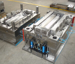
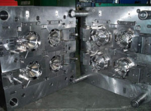
The mold format plan from oem/odm medical injection moulding factory is striking for two different reasons. In the first place, this plan shows 16 center supplements stuffed straightforwardly in a 4×4 lattice in one huge pocket in the center plate with no interceding mold steel. This plan is considerably more minimal and less expensive to create than a plan with 16 individual pockets for the center additions. Be that as it may, the plan will require cautious machining, completing, and gathering of the form embeds since resilience issues can cause positional mistakes and issues during embellishment, for example, coolant spills, blazing at the splitting line, or out of resistance shaped parts. Second, the plan of plastic injection mold manufacturers china is a family shape in which each set of eight holes is formed with various thicknesses and at various dissolve pressures. Planning the hot sprinter feed framework would be testing. A stacked “X” type complex like the plan of Fig. 6.13 could be utilized with various measurements for the essential sprinters to ba spear the dissolve pressures during filling.

In any case, given the diverse part thicknesses and comparable pressing factors gave to every one of the depressions, the form creator ought to anticipate less shrinkage in the more slender cover moldings and indicate a lower shrinkage esteem appropriately.

The portrayed examination strategies give sensible direction to mold plan. Then again, underlying reenactments utilizing limited component investigation can be performed utilizing the definite shape math. Such underlying examination procedures [5, 6] are getting progressively coordinated with PC stream reenactments to give high-constancy expectations while likewise decreasing huge hindrances to routine execution.

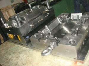
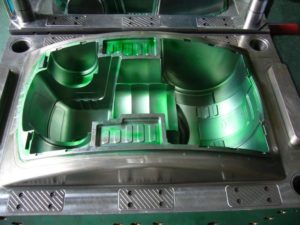
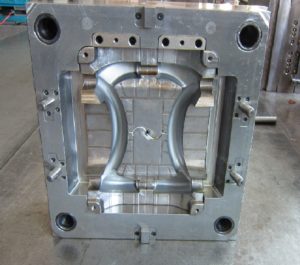
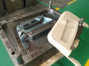
The previous examination zeroed in on plate avoidance across the splitting plane. In any case, the shear stresses in the side dividers of the shape plates can likewise bring about abundance avoidance and even disappointment. This worry turns out to be particularly critical for molds with profound depressions. The cup form addresses a common situation with the heap case appeared in china large size mold. In particular, the profound pit gives a tall side divider along which the liquefy pressure, P, is applied. Assuming the pit is profound, critical shear stresses and twisting diversions can create. The width of the side divider, from the outside of the form depression to the side of the shape, is for the most part alluded to as the”cheek.”

A typical rule in form configuration is that the width of the cheek, Wcheek, ought to be equivalent to the tallness of the shape cavity, Hcavity. The most extreme shear pressure in the side divider can be assessed as a component of the stature of the shape hole, Hcavity, the width of the cheek, Wcheek, and the embellishment pressure.

Appropriately, the general guideline that the width of the cheek should rise to the thickness of the hole gives a slight factor of security under run of the mill suppositions. Despite the fact that the shear pressure may not surpass as far as possible, the form planner ought to likewise check the diversion of the side divider under load. Accepting that the side divider goes about as a just upheld pillar with a uniform burden, at that point the redirection because of twisting of the side divider can be assessed. This article is from www.injectionmouldchina.com.

Cooling Interference

The launch stage devours valuable seconds of the trim cycle, without offering a lot of benefit to the moldings. Thusly, the launch framework ought to be intended to eliminate the moldings as fast and dependably as could reasonably be expected, and afterward reset with the goal that the form might be shut and the following cycle started. To speed up the launch framework of china mould manufacturing manufacturers, some disintegrates may determine the utilization of air poppets or potentially air planes to build part discharge speeds and diminish the process duration.

To expand the unwavering quality of the discharge framework, the shape originator ought to build up the form to firmly interface with the decay’s favored part expulsion framework. While numerous molds depend on gravity drop of the moldings and the feed framework to a moving transport, disintegrates are expanding utilizing sprue pickers and gantry robots for part evacuation. When all is said in done, these frameworks don’t significantly lessen the embellishment process duration but instead give expanded control of trim’s evacuation and resulting situation while ensuring the tasteful territories. On the off chance that sprue pickers or robots will be utilized, at that point the shape architect should properly tweak the launch framework.

Ordinarily, the ejectors are utilized to peel the moldings off the center yet then hold the moldings at a controlled position. Besides, form originators ought to affirm and plan interface math in the pit and additionally feed framework that is effortlessly distinguished and exceptionally repeatable for interfacing with the part expulsion framework.

china high-precision tooling factory to Minimize Cooling Interference

There can be numerous parts in a launch framework and, shockingly, the vast majority of these segments are not effectively cooled. Thusly, the discharge framework segments can essentially meddle with the warmth move way from the embellishment to the coolant. There are two issues that usually emerge. To begin with, the launch framework segments can be made of a solidified steel that is less thermally conductive than the center supplements. In the event that the discharge framework segments are huge, at that point the form’s cooling viability will be significantly decreased. Second, the launch framework segments are gathered into the form and gave sliding fits. The outcome is that there is a warm contact obstruction over each limit between the ejection framework segments and the contiguous form. This warm contact opposition brings about lower paces of warmth move through and around segments in the discharge framework.

The impact of cooling obstruction by the discharge framework can be critical to molds & tooling services china. Consider, for instance, an ejector pin with a measurement more prominent than the ostensible divider thickness of the trim. For this situation, the ejector pin won’t move critical warmth from the connecting surface of the embellishment since

■the ejector pin has a warm contact obstruction among it and the form, and

■the ejector pin is moderately enormous.

Subsequently, the plastic in the shape pit over the ejector pin should cool by means of warmth move to the form steel around the outskirts of the ejector pin just as warmth move to the contrary side of the form, While the nearby cooling of this definite territory of the trim may not be the huge requirement on the process duration, the outcome is that this enormous ejector pin will cause a problem area in the form and less steady properties upon discharge.

Thus, the utilization of excessively enormous ejector pins by injection mold manufacturing china ought to be dodged for different, more modest ejector pins put in order to not meddle with the shape cooling. Here and there, huge launch framework segments including stripper plates, lifters, center pulls, and others are required. Such enormous segments ought to be fitted with cooling channels and effectively cooled to give predictable launch temperatures.

This article is from https://www.injectionmouldchina.com

Shrinkage

Plastic part originators regularly use plan for assembling and get together (DFMA) rules to lessen the quantity of parts in a gathering for injection mold manufacturing china. Hence, plastic part plans can be incredibly perplexing with numerous highlights and tight resistances.

The conveyance of plastic moldings that fulfill the dimensional prerequisites is a joint duty of the form architect, disintegrate, material provider, and part planner. The part planner ought to furnish a plan with uniform thicknesses and reachable determinations. The material provider ought to give steady polymer tar and helpful direction with respect to material properties. The disintegrate should choose reasonable and reliable handling conditions for activity of the shape. The form planner ought to furnish a shape with adjusted liquefy filling and cooling, and for which the form cavity measurements were designed for a suitable shrinkage.

The shrinkage of shaped plastic parts is administered essentially by the warm withdrawal of the plastic, the compressibility of the plastic at pressing weights, and less significantly by the warm development of the form metal. The grouping of steps that decides the last part measurements is appeared in double coler mold parts manufacturers. Preceding embellishment, the form cavity measurements may change somewhat from the machined measurements given that the shape might be at a coolant temperature over the room temperature. The warm extension of the shape cavity, shown by the ran lines in mold manufacturer factory, can be assessed as the shape metal’s coefficient of warm extension increased by the temperature contrast between the form coolant and room temperature. For a P20 form embed, the coefficient of warm extension is 12.8. 10-6 m/m°C. In the case of embellishment ABS, the shape working temperatures may be 60°C, which is 40°C above room temperature. In that capacity, warm extension of the form pit is assessed as 0.0005 m/m or 0.05%(12.8.10-6 m/m°C times 40°C).

While this adjustment in form measurements is little contrasted with the greatness of shrinkage of the plastic, it is promptly anticipated and ought to be viewed as while indicating the last shape pit measurements for tight resistance applications.

During the filling and pressing phases of the trim cycle, the dissolve in the shape cavity is compelled by the surfaces of the form pit and packed at high weights. These high weights cause stresses, σ, that would make the liquefy in the shape depression grow if not contained by the form hole. During in-shape cooling, the temperature of the dissolve drops. In most trim cycles, the warm constriction of the dissolve causes the rot of the liquefy weight and arrival of related compressive anxieties. Ensuing cooling of the soften causes critical warm constriction. The trim will truly contract in the shape through the thickness and along any unconstrained surfaces, for example, ribs and side dividers. In certain zones of the part, nonetheless, the shrinkage of the plastic is obliged by side dividers. In these regions, the plastic doesn’t recoil so all things being equal creates interior tractable remaining anxieties.

Upon launch, a significant part of the formed in stresses are delivered, and the plastic embellishment promptly shrivels when it is pushed off the shape center. Further post form cooling permits the embellishment to equilibrate at room temperature and extra unwinding of any remaining pressure. In the model appeared in china precision plastic injection mold factory, the complete change long, AL, was – 0.005 m/m. This general decrease of the part length, Lmolding, from the planned shape depression measurement, Lcawity, is alluded to as the shrinkages.

The adjustment long of the embellishment because of shrinkage during the trim cycle is huge in most embellishment applications, and ought to be represented during the shape configuration measure. The capacity of a disintegrate to give tight resiliences is firmly identified with the shrinkage during embellishment [3]. Resistances on plastic part measurements are commonly determined as a level of their ostensible length. For example, the Society of the Plastics Industry gives rules about norm and tight resistances in business creation [4]. A commonplace resilience might be indicated as 土0.4% while an average tight resistance may be + 0.1%. In either case, a 0.5% shrinkage rate will make the embellishment be out of resilience. All things considered, the shape fashioner must consider the plastic shrinkage while indicating the form cavity measurements. In the event that the shape fashioner realized that the net shrinkage was 0.5 %, at that point the form pit measurement would be set to 100.5 mm to create a trim 100 mm long.

This article is from https://www.injectionmouldchina.com

Induction Heating

Induction heating is another way to deal with expanding the mold divider temperature before shape flling, and is seeing expanded application for micromolding, gleam, and quality. One plan is appeared in mould manufacturers china; this was created to infusion mold fortified thermoplastic composites with prevalent surface gleam and considerably no surface demoldities. T0 lessen energy utilization and warming time and high precision plastic injection mould price, just a little segment of the shape’s surface is specifically warmed by high-recurrence enlistment warming. As appeared in Fig. 9.30, a regular infusion molding machine 3 conveys polymer soften to a shape comprising of a fixed mold half 4 and a versatile shape half 5.

Preceding mold conclusion and flling, a high-recurrence oscillator 1 drives substituting current through an inductance curl (inductor) 2 briefly positioned close the surface(s) of the mold. At the point when a high-recurrence rotating current is gone through the inductor 2, an electromagnetic field is created around the inductor, which along these lines produces swirl flows inside the metal. The obstruction of the shape metal along these lines prompts interior Joule warming of the mold surface. Follows An and B in high precision mould china exhibit the expanded shape surface temperature at areas An and B brought about by induction heating; follows C and D show no underlying impact at area C and D away from the enlistment warming however later increment with the warmth move from the infused polymer soften into the mold pit.

Similarly as with all the recently portrayed methodologies for shape divider temperature control, decays wish to raise the surface temperature of the mold as fast as could reasonably be expected. The warming force through a high recurrence induction heating is relative to the square of the substituting recurrence, the square of the current, and the square of the curl thickness, among different components like china inner part mould manufacturers. In that capacity, the inductors must be painstakingly intended to locally warm the shape surface in a controlled way to keep away from an unwanted temperature circulation. For instance, an inductor was produced using copper container of 5 mm distance across and twisted as a winding with a pitch of 5 mm. The separation between the outside of the metal shape and the inductor was set to 1 cm. Analyses demonstrated that a driving recurrence of 400 kHz yielded a warming force at the mold surface on the request for 1000 W/cm2, which required roughly 10s to expand the outside of the shape by 50°C.

Contrasted with beat cooling and conduction warming, enlistment warming accommodates expanded warming rates with little included shape unpredictability. The essential issue in usage is the plan of the inductor, and specifically the dividing of its curl windings and their connection to the mold surfaces. In the event that the plan is ill-advised, at that point the warming might be restricted to low power levels. Tests showed that a warming force under 100 W/cm2 didn’t altogether build the shape surface temperature and in the long run made the over-burden breaker incite. Then again, when the force yield surpassed 10,000 W/cm2, the pace of the surface temperature increment turned out to be too steep to even consider controlling with the end goal that uniform warming was not, at this point potential; imperfections, for example, gleam abnormalities, sink marks, and so forth were seen with temperature contrasts of more than 50°C over the outside of the mold.

This article is from https://www.injectionmouldchina.com

Cavity Filling Prediction

The material cost, handling cost, and natural effect of molded parts are totally diminished with decreases in divider thickness. In any case of injection mold manufacturing china, limiting the divider thickness can make the mold cavity hard to fill and antagonistically increment clip weight. To gauge the compel needed to fill a mold, the form architect must know the complete separation that the stream is needed to head out to fill the mold. Hence, the mold creator should choose the gating location(s) to adjust the stream between the various parts of the form. Since this is a one-dimensional stream investigation, highlights, for example, ribs and managers are ignored. These highlights are probably going to fill on the off chance that they are moderately little contrasted with the essential stream way.

Forecast of the weight drop over the form cavity, OP, can be made given the stream length and the straight stream speed of the dissolve by use of either Eq. 5.17 or 5.22. The essential suspicion in the assessment of filling pressures is that the dissolve speed will be kept up at a consistent incentive as the liquefy proliferates from the entryway to the furthest limit of the form. In principle, such a uniform soften speed could be accomplished via cautious smash speed profiling. Practically speaking, complex form calculations block the acknowledgment of uniform soften speeds, and smash speed profiling is only from time to time utilized towards this reason in any case. Accordingly, the liquefy speed will fluctuate generously from the door (where the speed is at first extremely high because of the little cross-sectional zone of the soften) to the point of end of fill. All things considered about china large size mold, the assessment of filling pressures is imperative to guaranteeing that the moldings can be made with the mold structure and the plastic materials utilized.

To anticipate the filling pressure in complex items physically by lay-level examination, it is important for china mould manufacturing manufacturers to deconstruct the calculation into a progression of basic sections. The stream in each section would then be able to be independently examined utilizing the Newtonian or force law models relating compel drop to stream rates in the fragment. Returning now to the PC bezel appeared in Fig. 5.1, it might be accepted that the streams on the left-hand and right-hand sides are symmetric. In like manner, the investigation will think about only 50% of the calculation. To do the examination, any turns in the bezel will initially be fixed. While this progression isn’t fundamental for the investigation, it stresses that the examination considers just the weight drop along the length course of the liquefy stream. Next, the edges are collapsed out to uncover extra stream that is needed to fill the vertical sides of the form cavity.

The door area has been chosen close to the middle area. The lay-ilat calculation for the PC bezel is then part into two stream fragments speaking to the stream to the upper and lower bits of the form. It ought to be noted

that it is conceivable to remember changes for the channel width, for example, smaller segments because of windows, as appeared in the center lay level on the correct side of Fig.5.12.

Areas of shifting thickness ought to likewise be broken out into various stream fragments. By investigating the stream in every one of these sections, it is conceivable to give excellent appraisals of the dissolve front areas and soften pressures as the liquefy fills the mold. Then again, areas of comparable width might be lumped together to rearrange the calculation of the stream rate and filling pressures as appeared in the right-most lay level.

The item creator and form fashioner may wish to consider the compel needed to fill for an assortment of divider thicknesses, stream rates, and liquefy temperatures. Figure 5.13 gives the assessed filling compel needed to fill the depression for a scope of divider thicknesses at the material’s mid-go liquefy temperature. The base divider thickness passable for a given infusion weight can be inferred as shown in Fig. 5.13. In particular, a line demonstrating the most extreme reasonable weight is put on the diagram with the base divider thickness happening at the crossing point of the weight bend, The examination in this example shows that the base divider thickness is 1.4 mm at a soften temperature of 240°C.

There are two significant ideas that ought to be perceived while limiting the divider thickness. To start with, the base divider thickness is an element of the dissolve temperature. It is suggested that mold fashioners utilize the mid-range temperature for investigation, since this saves the open door for the disintegrate to expand dissolve temperature and consequently decrease the filling pressures if necessary. Second, the base divider thickness is likewise a component of the feed framework plan, since the weight deliverable to the cavity from the machine is subject to the weight drop through the feed framework.

This article is from https://www.injectionmouldchina.com.

Injection Molding Runner Design in China

The Advantages Of Good Runner Designs To Help Injection Molding

The plastic injection molding process in China is possible because any thermoplastic material can be melted to a predetermined size and the Injection molding machinery is designed such that it can then be injected into a mold or cavity where it can be formed. The parts of the mold which are in the shape of the parts to be manufactured are the cavities. The formed part is then ejected from the injection mold.

The sprue is a part of the runner which injects molten liquid plastic material into the die or Chinese mold through the injection machine’s nozzle. The runner system, as well as the sprue, is the passage that connects the nozzle of the machine to the mold cavities. Runner connects the sprue with the cavity through the gate.  The nozzle of the machine is connected to the runner by the sprue and come in designs of hot sprue or cold sprue.

Injection Molding Runner Design in China

The Injection molding runner design comes in three basic types – hot runner, insulated runner, and cold runner. The runner has to ensure that the liquid material is distributed so that it fills all the China molds under the same conditions and the same pressure at the same time. This will help to prevent flashing of the china injection mold and also helps in producing parts of a uniform and improved quality. Hot runner technology, which is externally heated is more practical and feasible since the plastic is maintained in a liquid state and most China mold makers use this technology.

The usage of hot runners in injection molding machinery is useful since it ensures better quality parts. They are particularly beneficial with uneven-shaped parts which might result in improper cooling or uneven flow. Hot runners also help in reducing plastic wastage.  They are designed to reduce cycle time, thus helping to maximize manufacturing productivity. The challenge in design is to maintain the liquid plastic which is molten at an optimum temperature while the china injection mold cavity is being cooled at the same time. Internal as well as external heating methods are used generally in injection molding machinery. Thus the hot runner technology, which was introduced almost 50 years before in the plastic industry, has revolutionized the china plastic injection molding technology and its processing capabilities by enhancing the efficiency of operation, improving the quality of the parts, reducing wastage and scrap and thus in effect saving money.

A very critical consideration for injection molding runner design as well as the china injection molding process is to maintain a uniform temperature in the hot-runner manifold and the sprue bar so as to ensure consistency in quality. Another consideration to be taken by China mold manufacturers is regarding the runner system. The injection mold china cavities will not be filled properly if the runner is too small. If the runner is too large, then cooling time will be increased and the cycle time will be decreased. Proper design for runners for injection molding china is most essential to reduce the effect of sink, stress, and weld marks.

A good and efficient runner design is most essential for plastic injection molding machinery as it helps in producing better quality parts at a very reasonable and affordable rate due to higher efficiency and lower wastage. Currently there are many suppliers who provide injection molding systems from China at very good quality.

Resource box: This article is originally posted in https://www.injectionmouldchina.com.

gas assisted injection mold in China

How to make gas assisted injection mold?

The gas-assisted injection molding is a process that involves the traditional, low-pressure process of injection molding. This process uses pressurized nitrogen gas to force material into a mold. Let’s find out more about gas-assisted injection molding.

gas assisted injection mold in China

Basically, this process is used to produce big parts of plastic using complex designs and beautiful surface finishes. Normally, this process is a great choice for making skins, cabinets, bezels, doors, equipment covers, and handles.

Internal Injection Molding

As said earlier, this process injects pressurized nitrogen gas into a mold. Actually the nitrogen gas is passed through the gas channels for displacing the material through the creation of hollow sections.

The molten resin is pushed against the wall of the cavity until the solidification of the path. The constant pressure of the gas prevents the shrinkage of the part. In addition, it reduces internal factors, sink marks, and surface blemishes. So, this process can work well to hold curvatures and tight dimensions.

External Injection Molding

In this type of injection molding, the material is pushed into the mold. However, the gas is pushed in a very thin layer between the mold core and the back surface of the component. So the front surface of the component is forced against the other side of the cavity of the mold. as the gas cools down, different sides of the component replicate the mold surface.

Basically, this process is suitable for plastic parts that feature large surface areas, especially those parts that require beautiful surface and detailed textures. In this process, the sink and warp marks are removed because in nitrogen gas maintains the material condition.

Just like internal gas assist, the bosses and support ribs are molded into the component and produce the same level of tolerance and dimensional stability. In the same way, molding pressure produces less stress wear and tear.

Cost Considerations

This process also helps save a lot of money. Typically, these processes require a lot less force than traditional injection molding. Therefor it helps reduce the component chords costs and produces less stress as well.

Actually, the mold pressure results in reduced wear and tear. Therefore, there would be less demand for pricey aluminum tooling. Moreover, the parts made are lightweight which will help reduce the freight expenses and boost material handling.

Design Benefits

Moreover, this technology results in a lot of performance and design benefits. For example, multiple parts with different thickness off walls can be molded.

Converting different components to Gas Assist

This type of injection molding is a better alternative to the large metal parts. Therefore, it is possible to eliminate expensive, heavyweight, corrosive components like panels, access doors, enclosures hand covers.

In short, this was a brief introduction to gas-assisted injection molding. Hopefully, this article will help you understand the concept much better.

Resource box: This article is originally posted in https://www.injectionmouldchina.com.

injection molding defects

How to eliminate injection molding defects?

Injection molding is an art, which involves science as well. Actually, injection molding requires great attention to detail as minor mistakes can cause a lot of financial loss to a company. In this article, we are going to discuss how you can eliminate common injection molding defects.

injection molding defects

Flow Lines

Flow lines may include lines, patterns, and streaks that appear on the prototype part because of the cooling profile or physical path of the molten plastic while it moves into the cavity.

Fix:

  • One way to fix the issue is to increase the pressure and injection speed, which will make sure that the mold will fill the cavities.
  • Another way is to round the locations and corners where the thickness of the wall changes.

Sink Marks

These are minor depressions or craters that form in the thicker areas when shrinkage happens in the internal areas of the end product.

Fix:

  • Reduce the mold temperature, increase the holding pressure and time for better curing and cooling.
  • Reduce the thickness of the wall sections that are the thickest. This will allow faster cooling and prevent the sink marks.

Vacuum Voids

Vacuum voids refer to the air pockets inside or near the prototype surface. They occur because of the uneven solidification amidst the inner sections and the surface.

Fix:

  • Find the gate at the mold’s thickest part
  • Opt for the plastic that is less viscous, which will reduce the amount of gas trapped.
  • Increase the holding time and pressure
  • Try to keep the mold parts aligned

Surface Delamination

Surface delamination happens when thin layers of the surface show up on the part because of a contaminant. Actually, these layers look like coats that can be peeled off.

Fix:

  • Before molding, make sure you dry the plastic properly
  • Raise the degree of mold temperature
  • There should no sharp turns and corners in the mold design

Weld Lines

Weld lines show up on an area where the liquid plastics mixes while they flow from different injection mold parts.

Fix

  • Increase the temperature of molten plastic or mold
  • Raise the injection speed
  • Make adjustments to the design to ensure that the flow pattern is only one source flow

Short Shot

Short shot refers to a situation that happens when a molding shot tends to fall short. In other words, the molten plastic won’t fill the cavity of the mold for some reason. As a result, it leaves a portion where you can see plastic.

Fix

  • Opt for a plastic that features higher flow and less viscosity
  • Raise the mold temperature for better flow
  • Get a machine that features more material feed

To cut a long story short, you may have to face a lot of defects during the process of injection molding in China. What you need to do is follow the tips given in this article to fix or eliminate these issues to make the process error free. Hopefully, you will find these tips helpful.

Resource box: This article is originally posted in https://www.injectionmouldchina.com.

injection mold cooling systems in china

What are injection mold cooling systems?

As far as the plastic molding process is concerned, the injection mold cooling system plays a great role. Actually, this system directly affects the production efficiency, machine speed and the quality of end product. In the case of semi-crystalline polymers and amorphous, the highest level of heat efficiency is required. Let’s know more about this system.

injection mold cooling systems in china

The Design of Injection Mold Cooling Systems

First off, it’s important to keep in mind that the design of this system is of paramount importance. In fact, the cooling time accounts for up to 80% of the cycle. If the cooling system is properly designed, it can reduce the molding time for better efficiency. On the other hand, if this system is poorly designed, the reverse may happen.

So, the question is, what factors should be kept in mind for effective cooling? Given below are some of the major factors.

Plastic wall-thickness

If the plastic thickness is higher, it will take much longer to cool down. As a general rule, the cooling time depends upon the thickness of the parts of plastic. Ideally, it’s better to keep the thickness as low as possible.

It’s possible to choose low thickness, but it may not be possible for all types of projects. So, if the project allows some flexibility, the designers should not go for a higher wall-thickness. This is the number factor on the list.

Mold steel

If the steel has a higher thermal conductivity, more heat can be transferred. As a result, the cooling time will shrink. Typically, China injection mold maker uses copper in place of steel in order to get better results.

The layout of the Cooling line

It’s better to keep the mold cavity near the cooling pipes. Also, it’s better to have cooling pipes with higher diameters for better cooling. Therefore, the designer should consider these parameters in order to enjoy the best cooling effect.

Coolant

As the name suggests, coolants are the things used to cool down the plastic parts. Designers use different types of coolants. The two most common ones are oil and water. In addition, the thermal conductivity and viscosity of the coolant may also have an impact on the heat conduction. If the fluid viscosity is low, the thermal conductivity will be high.

The rules of designing a Cooling system

  • Ensuring highest cooling efficiency
  • Ensuring consistent cooling in order to avoid deformation of the objects
  • Facilitating the process of manufacturing

The goal of the cooling system is to ensure faster dissipation of heat from the objects. This ensures the best physical and dimensional properties. This requires a solid engineering approach in order to measure the injection mold performance with the help of water circuits.

Long story short, this is not a thorough list of factors that should be kept in mind when designing the perfect cooling system for injection molding company in China. However, with the help of this approach and good engineering knowledge, designers can get the best results. This will help them employ the right engineering practices and tools.

Resource box: This article is originally posted in https://www.injectionmouldchina.com.

hot runner injection mold in China

What Are The Purposes Of Hot Runner In Making Plastic Injection Molds?

Basically, the injection molding process has been used the traditional way, which is known as the cold runner system. Nowadays, another method is getting popular. It’s known as the hot runner system. In this process, liquid substrate is put into the mold via a nozzle. So, the runner is kind of a passage through which the material travels. During the process, the substrate doesn’t cool down or get hard. Let’s find out why most people go for the hot runner for their plastic injection molds.

hot runner injection mold in China

During a hot runner process, the mold is heated up and then cooled down once all of the cavity is full. Remember: the hot runner process may use many ways to heat up the injection mold, such as hot oil, hot water, induction/steam heating for quick heating. Unlike the cold runner system, this system cause fewer issues.

Now, let’s discuss why people go for the hot runner system in the injection molding process.

Less waste: This is an important point. In the hot runner system, the substance that passes through the chambers remains hot even when it reaches the last stage. In the cold molding, on the other hand, the runner is either discarded (waste) or recycled/reground. This is a disadvantage.

Quick cycle: As said earlier, the runner process requires time and may cause a loss of resource if enough time is not given. By fixing these problems, the hot runner system can boost the cycle times.

Keep in mind that the cooling and heating mold takes more time. Often, the time is offset through the savings from the elimination of the runner. However, it’s better to discuss the topic with your service provider.

Quality output: the removal of runners from the cold molded components requires a mechanical process. The product may get rejected if it is not up to the mark. In other words, the look and function of the product should be acceptable.

On the other hand, the hot molding can help resolve many issues, such as surface irregularities and burn marks, just to name a few.

Lower costs: cost is an importance consideration when opting for a cold or hot molding for a long-term. The initial cost of cold molding is less but the hot the hot runner system is a cost effective option as far as the long-term use is concerned.

Range of material: Actually, the inherent chemical composition of most of injection molding substance makes them a bit too “allergic” to temperature changes. The impact is stronger in extreme temperatures. So, for lower temperatures, the hot runner system is the way to go.

Colorant options: The hot runner system allows you to benefit from colorant mixtures in the process. So, this is another reason people opt for the hot runner process.

Long story short, these are the reasons the hot runner is an ideal choice for the majority of plastic injection mold projects. If you are looking to increase production in an efficient manner, we suggest that you give a go to this process. Hope this helps.

When it comes to hot runner injection mold, china plastic injection molding is the best choice.

Resource box: This article is originally posted in https://www.injectionmouldchina.com.