Klarm Mould Promotes Molding Design Service

Klarm Mould offers injection moulding design china and molds & tooling services china.

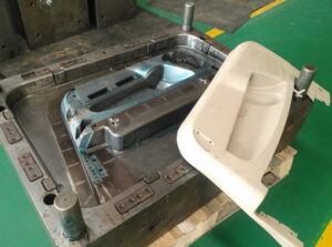
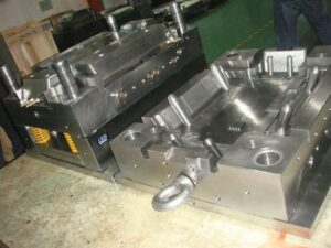
The mold format plan from oem/odm medical injection moulding factory is striking for two different reasons. In the first place, this plan shows 16 center supplements stuffed straightforwardly in a 4×4 lattice in one huge pocket in the center plate with no interceding mold steel. This plan is considerably more minimal and less expensive to create than a plan with 16 individual pockets for the center additions. Be that as it may, the plan will require cautious machining, completing, and gathering of the form embeds since resilience issues can cause positional mistakes and issues during embellishment, for example, coolant spills, blazing at the splitting line, or out of resistance shaped parts. Second, the plan of plastic injection mold manufacturers china is a family shape in which each set of eight holes is formed with various thicknesses and at various dissolve pressures. Planning the hot sprinter feed framework would be testing. A stacked “X” type complex like the plan of Fig. 6.13 could be utilized with various measurements for the essential sprinters to ba spear the dissolve pressures during filling.
In any case, given the diverse part thicknesses and comparable pressing factors gave to every one of the depressions, the form creator ought to anticipate less shrinkage in the more slender cover moldings and indicate a lower shrinkage esteem appropriately.

The portrayed examination strategies give sensible direction to mold plan. Then again, underlying reenactments utilizing limited component investigation can be performed utilizing the definite shape math. Such underlying examination procedures [5, 6] are getting progressively coordinated with PC stream reenactments to give high-constancy expectations while likewise decreasing huge hindrances to routine execution.

The previous examination zeroed in on plate avoidance across the splitting plane. In any case, the shear stresses in the side dividers of the shape plates can likewise bring about abundance avoidance and even disappointment. This worry turns out to be particularly critical for molds with profound depressions. The cup form addresses a common situation with the heap case appeared in china large size mold. In particular, the profound pit gives a tall side divider along which the liquefy pressure, P, is applied. Assuming the pit is profound, critical shear stresses and twisting diversions can create. The width of the side divider, from the outside of the form depression to the side of the shape, is for the most part alluded to as the”cheek.”

A typical rule in form configuration is that the width of the cheek, Wcheek, ought to be equivalent to the tallness of the shape cavity, Hcavity. The most extreme shear pressure in the side divider can be assessed as a component of the stature of the shape hole, Hcavity, the width of the cheek, Wcheek, and the embellishment pressure.

Appropriately, the general guideline that the width of the cheek should rise to the thickness of the hole gives a slight factor of security under run of the mill suppositions. Despite the fact that the shear pressure may not surpass as far as possible, the form planner ought to likewise check the diversion of the side divider under load. Accepting that the side divider goes about as a just upheld pillar with a uniform burden, at that point the redirection because of twisting of the side divider can be assessed. This article is from www.injectionmouldchina.com.

Shrinkage

Plastic part originators regularly use plan for assembling and get together (DFMA) rules to lessen the quantity of parts in a gathering for injection mold manufacturing china. Hence, plastic part plans can be incredibly perplexing with numerous highlights and tight resistances.

The conveyance of plastic moldings that fulfill the dimensional prerequisites is a joint duty of the form architect, disintegrate, material provider, and part planner. The part planner ought to furnish a plan with uniform thicknesses and reachable determinations. The material provider ought to give steady polymer tar and helpful direction with respect to material properties. The disintegrate should choose reasonable and reliable handling conditions for activity of the shape. The form planner ought to furnish a shape with adjusted liquefy filling and cooling, and for which the form cavity measurements were designed for a suitable shrinkage.

The shrinkage of shaped plastic parts is administered essentially by the warm withdrawal of the plastic, the compressibility of the plastic at pressing weights, and less significantly by the warm development of the form metal. The grouping of steps that decides the last part measurements is appeared in double coler mold parts manufacturers. Preceding embellishment, the form cavity measurements may change somewhat from the machined measurements given that the shape might be at a coolant temperature over the room temperature. The warm extension of the shape cavity, shown by the ran lines in mold manufacturer factory, can be assessed as the shape metal’s coefficient of warm extension increased by the temperature contrast between the form coolant and room temperature. For a P20 form embed, the coefficient of warm extension is 12.8. 10-6 m/m°C. In the case of embellishment ABS, the shape working temperatures may be 60°C, which is 40°C above room temperature. In that capacity, warm extension of the form pit is assessed as 0.0005 m/m or 0.05%(12.8.10-6 m/m°C times 40°C).

While this adjustment in form measurements is little contrasted with the greatness of shrinkage of the plastic, it is promptly anticipated and ought to be viewed as while indicating the last shape pit measurements for tight resistance applications.

During the filling and pressing phases of the trim cycle, the dissolve in the shape cavity is compelled by the surfaces of the form pit and packed at high weights. These high weights cause stresses, σ, that would make the liquefy in the shape depression grow if not contained by the form hole. During in-shape cooling, the temperature of the dissolve drops. In most trim cycles, the warm constriction of the dissolve causes the rot of the liquefy weight and arrival of related compressive anxieties. Ensuing cooling of the soften causes critical warm constriction. The trim will truly contract in the shape through the thickness and along any unconstrained surfaces, for example, ribs and side dividers. In certain zones of the part, nonetheless, the shrinkage of the plastic is obliged by side dividers. In these regions, the plastic doesn’t recoil so all things being equal creates interior tractable remaining anxieties.

Upon launch, a significant part of the formed in stresses are delivered, and the plastic embellishment promptly shrivels when it is pushed off the shape center. Further post form cooling permits the embellishment to equilibrate at room temperature and extra unwinding of any remaining pressure. In the model appeared in china precision plastic injection mold factory, the complete change long, AL, was – 0.005 m/m. This general decrease of the part length, Lmolding, from the planned shape depression measurement, Lcawity, is alluded to as the shrinkages.

The adjustment long of the embellishment because of shrinkage during the trim cycle is huge in most embellishment applications, and ought to be represented during the shape configuration measure. The capacity of a disintegrate to give tight resiliences is firmly identified with the shrinkage during embellishment [3]. Resistances on plastic part measurements are commonly determined as a level of their ostensible length. For example, the Society of the Plastics Industry gives rules about norm and tight resistances in business creation [4]. A commonplace resilience might be indicated as 土0.4% while an average tight resistance may be + 0.1%. In either case, a 0.5% shrinkage rate will make the embellishment be out of resilience. All things considered, the shape fashioner must consider the plastic shrinkage while indicating the form cavity measurements. In the event that the shape fashioner realized that the net shrinkage was 0.5 %, at that point the form pit measurement would be set to 100.5 mm to create a trim 100 mm long.

This article is from https://www.injectionmouldchina.com

Induction Heating

Induction heating is another way to deal with expanding the mold divider temperature before shape flling, and is seeing expanded application for micromolding, gleam, and quality. One plan is appeared in mould manufacturers china; this was created to infusion mold fortified thermoplastic composites with prevalent surface gleam and considerably no surface demoldities. T0 lessen energy utilization and warming time and high precision plastic injection mould price, just a little segment of the shape’s surface is specifically warmed by high-recurrence enlistment warming. As appeared in Fig. 9.30, a regular infusion molding machine 3 conveys polymer soften to a shape comprising of a fixed mold half 4 and a versatile shape half 5.

Preceding mold conclusion and flling, a high-recurrence oscillator 1 drives substituting current through an inductance curl (inductor) 2 briefly positioned close the surface(s) of the mold. At the point when a high-recurrence rotating current is gone through the inductor 2, an electromagnetic field is created around the inductor, which along these lines produces swirl flows inside the metal. The obstruction of the shape metal along these lines prompts interior Joule warming of the mold surface. Follows An and B in high precision mould china exhibit the expanded shape surface temperature at areas An and B brought about by induction heating; follows C and D show no underlying impact at area C and D away from the enlistment warming however later increment with the warmth move from the infused polymer soften into the mold pit.

Similarly as with all the recently portrayed methodologies for shape divider temperature control, decays wish to raise the surface temperature of the mold as fast as could reasonably be expected. The warming force through a high recurrence induction heating is relative to the square of the substituting recurrence, the square of the current, and the square of the curl thickness, among different components like china inner part mould manufacturers. In that capacity, the inductors must be painstakingly intended to locally warm the shape surface in a controlled way to keep away from an unwanted temperature circulation. For instance, an inductor was produced using copper container of 5 mm distance across and twisted as a winding with a pitch of 5 mm. The separation between the outside of the metal shape and the inductor was set to 1 cm. Analyses demonstrated that a driving recurrence of 400 kHz yielded a warming force at the mold surface on the request for 1000 W/cm2, which required roughly 10s to expand the outside of the shape by 50°C.

Contrasted with beat cooling and conduction warming, enlistment warming accommodates expanded warming rates with little included shape unpredictability. The essential issue in usage is the plan of the inductor, and specifically the dividing of its curl windings and their connection to the mold surfaces. In the event that the plan is ill-advised, at that point the warming might be restricted to low power levels. Tests showed that a warming force under 100 W/cm2 didn’t altogether build the shape surface temperature and in the long run made the over-burden breaker incite. Then again, when the force yield surpassed 10,000 W/cm2, the pace of the surface temperature increment turned out to be too steep to even consider controlling with the end goal that uniform warming was not, at this point potential; imperfections, for example, gleam abnormalities, sink marks, and so forth were seen with temperature contrasts of more than 50°C over the outside of the mold.

This article is from https://www.injectionmouldchina.com

Cavity Filling Prediction

The material cost, handling cost, and natural effect of molded parts are totally diminished with decreases in divider thickness. In any case of injection mold manufacturing china, limiting the divider thickness can make the mold cavity hard to fill and antagonistically increment clip weight. To gauge the compel needed to fill a mold, the form architect must know the complete separation that the stream is needed to head out to fill the mold. Hence, the mold creator should choose the gating location(s) to adjust the stream between the various parts of the form. Since this is a one-dimensional stream investigation, highlights, for example, ribs and managers are ignored. These highlights are probably going to fill on the off chance that they are moderately little contrasted with the essential stream way.

Forecast of the weight drop over the form cavity, OP, can be made given the stream length and the straight stream speed of the dissolve by use of either Eq. 5.17 or 5.22. The essential suspicion in the assessment of filling pressures is that the dissolve speed will be kept up at a consistent incentive as the liquefy proliferates from the entryway to the furthest limit of the form. In principle, such a uniform soften speed could be accomplished via cautious smash speed profiling. Practically speaking, complex form calculations block the acknowledgment of uniform soften speeds, and smash speed profiling is only from time to time utilized towards this reason in any case. Accordingly, the liquefy speed will fluctuate generously from the door (where the speed is at first extremely high because of the little cross-sectional zone of the soften) to the point of end of fill. All things considered about china large size mold, the assessment of filling pressures is imperative to guaranteeing that the moldings can be made with the mold structure and the plastic materials utilized.

To anticipate the filling pressure in complex items physically by lay-level examination, it is important for china mould manufacturing manufacturers to deconstruct the calculation into a progression of basic sections. The stream in each section would then be able to be independently examined utilizing the Newtonian or force law models relating compel drop to stream rates in the fragment. Returning now to the PC bezel appeared in Fig. 5.1, it might be accepted that the streams on the left-hand and right-hand sides are symmetric. In like manner, the investigation will think about only 50% of the calculation. To do the examination, any turns in the bezel will initially be fixed. While this progression isn’t fundamental for the investigation, it stresses that the examination considers just the weight drop along the length course of the liquefy stream. Next, the edges are collapsed out to uncover extra stream that is needed to fill the vertical sides of the form cavity.

The door area has been chosen close to the middle area. The lay-ilat calculation for the PC bezel is then part into two stream fragments speaking to the stream to the upper and lower bits of the form. It ought to be noted

that it is conceivable to remember changes for the channel width, for example, smaller segments because of windows, as appeared in the center lay level on the correct side of Fig.5.12.

Areas of shifting thickness ought to likewise be broken out into various stream fragments. By investigating the stream in every one of these sections, it is conceivable to give excellent appraisals of the dissolve front areas and soften pressures as the liquefy fills the mold. Then again, areas of comparable width might be lumped together to rearrange the calculation of the stream rate and filling pressures as appeared in the right-most lay level.

The item creator and form fashioner may wish to consider the compel needed to fill for an assortment of divider thicknesses, stream rates, and liquefy temperatures. Figure 5.13 gives the assessed filling compel needed to fill the depression for a scope of divider thicknesses at the material’s mid-go liquefy temperature. The base divider thickness passable for a given infusion weight can be inferred as shown in Fig. 5.13. In particular, a line demonstrating the most extreme reasonable weight is put on the diagram with the base divider thickness happening at the crossing point of the weight bend, The examination in this example shows that the base divider thickness is 1.4 mm at a soften temperature of 240°C.

There are two significant ideas that ought to be perceived while limiting the divider thickness. To start with, the base divider thickness is an element of the dissolve temperature. It is suggested that mold fashioners utilize the mid-range temperature for investigation, since this saves the open door for the disintegrate to expand dissolve temperature and consequently decrease the filling pressures if necessary. Second, the base divider thickness is likewise a component of the feed framework plan, since the weight deliverable to the cavity from the machine is subject to the weight drop through the feed framework.

This article is from https://www.injectionmouldchina.com.