Reverse Ejection

The depression embeds in many molds are situated inside the fixed side of the form and the center additions are situated on the moving side of the shape. Since the formed part contracts onto the centers as the plastic cools, the shaped parts will in general stay with the centers on the moving side of the form when the shape is opened.

Appropriately, molds are normally planned with an ejector lodging and ejector plate on the moving side of the shape to such an extent that ejector pins can eliminate the part from the center. In any case, this ordinary plan from china high precision mold manufacturer is tricky in that it doesn’t accommodate a simply stylish surface, totally liberated from abandons, on one or the other side of the formed part. Witness imprints will ordinarily be left on the center side of the formed part from the ejector pins while witness imprints will commonly be left on the depression side of the shaped part from the feed framework.

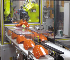
To give a totally tasteful surface, molds can be planned with “switch launch.” One such plan is appeared in oem/odm automotives molding factory, which incorporates a form hole plate 68 on the moving side of the shape and a form center plate 38 on the fixed side of the shape 36. The sprue 76 passes on the plastic liquefy from the machine spout 14 through the shape center plate 38 to the form cavity 40 and 74. Since the shaped part will in general stay on the form center, the fixed side of the form 36 likewise incorporates ejector pins 48 and different segments that work with an ejector plate 30 situated between rails 18. Since the trim machine’s ejector pole is situated on the moving side of the embellishment machine and is futile with this shape plan, the form configuration likewise incorporates water driven chambers 32 for incitation of the ejector plate. Because of this shape plan, the whole surface of the formed part inverse the center is liberated from restorative imperfections.

There are points of interest and inconveniences of the shape plan of oem/odm industrial injection mold factory contrasted with the past plan of china mold component machining. The essential preferred position is the utilization of various equipping stages to decouple the incitation of the rack and pinion from the turn of the centers. All things considered, it is conceivable to defer and in any case program the pivot of the centers during the form opening while at the same time evading the exceptionally huge stack stature related with the coarse helix of the past plan. The essential burden is the enormous number, complex design, and huge volume of the outfitting stages. Furthermore, the planetary design proposes an outspread format of pits thus may require extremely enormous molds for a high number of holes. Appropriately, the planetary stuff configuration might be ideal in a shape with a moderately low number of cavities requiring high incitation forces.

This article is from https://www.injectionmouldchina.com/

Ejector

The utilization of a molded ejector pin configuration requires cautious ejector pin configuration just as cautious arrangement of the ejector pin to the part includes. Besides, there is a potential issue that can emerge with the utilization of formed ejectors stretching out external the splitting line of the shape pit as shown in oem/odm industrial injection mold factory. In particular, in the event that the ejector pin is too short, at that point a hole will shape between the highest point of the ejector pin and the contrary surface of the pit embed. In the event that this hole is bigger than the thickness of a vent, at that point streak is probably going to happen. In the interim, in the event that the ejector pin is too long, at that point the pin will meddle with the restricting plate and be packed upon shape conclusion. With rehashed discharge cycles, the pin can exhaustion and clasp. Given that the necessary length of the ejector pin is hard to definitely decide because of the stack-up in resistances over the form get together, the shape fashioner may wish to utilize a”steel-safe” approach with various length changes. Then again, the shape architect may decide to put the ejector pin inside the form cavity and shape the pin with respect to the rib in china mold component machining. In these cases, slight blunders in the shape of the pin will be on non-aesthetic surfaces as be less huge as for the nature of the embellishment.

After the number, format, and math of the ejectors have been resolved, the detailing of the plan should be finished to guarantee hearty shape gathering and activity, There are a few unmistakable issues that should be tended to. To start with, the form architect ought to perceive that the shape gathering is muddled by the enormous number of ejector framework segments that must be at the same time mated to the center supplements. This issue is compounded by resistance stack-up over various plates in the form gathering. Taken together, the shape gathering can devour a decent measure of time and result in harm of important form parts.

To encourage the form get together, cautious enumerating is required any place the ejector framework segments interface with different parts in the shape. mold manufacturing factory gives a top and area perspective on a round ejector pin (left) and a molded ejector pin (right). china automatives injection overmould manufacturers shows that a leeway can be given between the pin and the drag of the ejector opening to vent uprooted air during the embellishment cycle. The investigation of the vent’s leeway was given in china high precision mold manufacturer, demonstrating that commonly a freedom of 0.02 mm (0.001 in) is accommodated a sliding bearing length of the request for a few widths of the ejector pin. Past this bearing length, the ejector opening should venture to a bigger size So as to not confine the sliding of the pin. The size of the leeway isn’t basic yet rather just restricted by the impedance with other close by parts. A chamfer should be given from the bigger distance across to the bearing/venting breadth.

Something else, the ejector pin would will in general hang up on the sharp corner during mold get together, which can hamper the shape gathering when attempting to find a large number of ejector pins.

This article is from https://www.injectionmouldchina.com

Induction Heating

Induction heating is another way to deal with expanding the mold divider temperature before shape flling, and is seeing expanded application for micromolding, gleam, and quality. One plan is appeared in mould manufacturers china; this was created to infusion mold fortified thermoplastic composites with prevalent surface gleam and considerably no surface demoldities. T0 lessen energy utilization and warming time and high precision plastic injection mould price, just a little segment of the shape’s surface is specifically warmed by high-recurrence enlistment warming. As appeared in Fig. 9.30, a regular infusion molding machine 3 conveys polymer soften to a shape comprising of a fixed mold half 4 and a versatile shape half 5.

Preceding mold conclusion and flling, a high-recurrence oscillator 1 drives substituting current through an inductance curl (inductor) 2 briefly positioned close the surface(s) of the mold. At the point when a high-recurrence rotating current is gone through the inductor 2, an electromagnetic field is created around the inductor, which along these lines produces swirl flows inside the metal. The obstruction of the shape metal along these lines prompts interior Joule warming of the mold surface. Follows An and B in high precision mould china exhibit the expanded shape surface temperature at areas An and B brought about by induction heating; follows C and D show no underlying impact at area C and D away from the enlistment warming however later increment with the warmth move from the infused polymer soften into the mold pit.

Similarly as with all the recently portrayed methodologies for shape divider temperature control, decays wish to raise the surface temperature of the mold as fast as could reasonably be expected. The warming force through a high recurrence induction heating is relative to the square of the substituting recurrence, the square of the current, and the square of the curl thickness, among different components like china inner part mould manufacturers. In that capacity, the inductors must be painstakingly intended to locally warm the shape surface in a controlled way to keep away from an unwanted temperature circulation. For instance, an inductor was produced using copper container of 5 mm distance across and twisted as a winding with a pitch of 5 mm. The separation between the outside of the metal shape and the inductor was set to 1 cm. Analyses demonstrated that a driving recurrence of 400 kHz yielded a warming force at the mold surface on the request for 1000 W/cm2, which required roughly 10s to expand the outside of the shape by 50°C.

Contrasted with beat cooling and conduction warming, enlistment warming accommodates expanded warming rates with little included shape unpredictability. The essential issue in usage is the plan of the inductor, and specifically the dividing of its curl windings and their connection to the mold surfaces. In the event that the plan is ill-advised, at that point the warming might be restricted to low power levels. Tests showed that a warming force under 100 W/cm2 didn’t altogether build the shape surface temperature and in the long run made the over-burden breaker incite. Then again, when the force yield surpassed 10,000 W/cm2, the pace of the surface temperature increment turned out to be too steep to even consider controlling with the end goal that uniform warming was not, at this point potential; imperfections, for example, gleam abnormalities, sink marks, and so forth were seen with temperature contrasts of more than 50°C over the outside of the mold.

This article is from https://www.injectionmouldchina.com

Interlocking Core

At the point when the part math permits, slim centers with little breadths can be interlocked with the contradicting mold cavity as appeared in Fig. 9.25. Such a plan from injection moulding design china has two preferences. In the first place, the interlocking of the center with the depression offers help for the center and will in general decrease the center flexture as broke down in oem/odm industrial injection mold factory. Second, the interlocking gives a methods by which to pass on coolant from the moving side of the shape, through the center, and to the fixed side of the form. Air is ordinarily utilized as the coolant in such a plan since this coolant will be presented to the shaped part and the climate when the form is opened. While air has a low thickness, which lessens its cooling viability, plan with air channels will give considerably more warmth move than a strong center pin.

There are two regular embellishment circumstances in which there is irrelevant warmth stream from one side of the trim. The first is the long slim center indicated before in china injection mold factory, which depends exclusively on conduction down the hub of the slim pin to move heat from within the embellishment. Since the pin is so thin, there will be very lttle heat move down the length of the pin. Thus, most of the warmth must be moved to the cooling lines in the depression embed.

pom moulding parts made in china plots the warmth motion in a form having a thin center pin. The transition vectors demonstrate that there is some noteworthy warmth move around the centerline of the pin towards the coolant at its base. Nonetheless, the pin’s cross-sectional zone is little to the point that there is an overwhelming outspread warmth motion at the outside of the pin. All in all, the hot plastic liquefy that is contacting the center must exchange a large portion of its warmth entirely through the plastic to the metal and cooling lines of the depression embeds.

As to the cooling of such slim centers, the form creator ought to comprehend that the cooling time will probably be stretched out because of the restricted warmth move to the coolant. A most dire outcome imaginable can be promptly examined by expecting that there is no warmth ransfer deeply. The warmth fIux in this situation is appeared in china high precision mold manufacturer. Since all the warmth must exchange through one side of the trim, the warm conduct is basically equivalent to if two layers of the plastic dissolve were on head of one another. This twofold thickness portrayal is legitimate since the temperature circulation is symmetric over the centerline so there is no related warmth motion.

Uneven warmth stream will likewise happen when forming a plastic layer on head of another material that is ineffectively conductive, as in two-shot (multishot) shaping or overmolding, In these cycles, the primary layer or item may go about as a cover that restricts the warmth stream from the polymer liquefy just injected. As in china mold component machining, the impact of the protecting layer is to confine the warmth stream to only one side of the polymer liquefy. To ascertain the warmth move rates for such uneven warmth streams, mold manufacturing factory might be utilized by subbing double the genuine thickness of the embellishment for the thickness variable, h. The net outcome is that any trim application with an uneven warmth stream will have roughly a four-overlap increment in the cooling time over an embellishment cooled from different sides.

This article is from https://www.injectionmouldchina.com

Thermal Gate

The utilization of a hot runner feed system by china molds produce services wipes out the requirement for the embellishment and cooling of a chilly runner. The plan of gates for hot runners  fluctuates considerably from those for cold runners. The essential targets are commonly the equivalent with respect to the shear rate, pressure drop, and tasteful necessities. Notwithstanding, warm entryways in hot runners should likewise give a set attachment that forestalls the condensed plastic dissolve in the hot runner from streaming out of the gate when the shape opens and the set plastic close to the gate is taken out with the embellishment.

One of the most common sorts of gates utilized by china high precision mold manufacturer in hot runners is the pin-point warm entryway framed with an internal”torpedo” .In this plan, a profoundly conductive torpedo is embedded into the spout close to the entryway. The motivation behind the torpedo is to communicate heat from the spout towards the entryway and keep the plastic liquid inside. Normally, at least two holes in the torpedo are utilized to pass on the plastic dissolve in the feed system into the depression. A slender layer of remaining plastic liquefy is utilized to protect the hot torpedo from the virus form dividers.

During the filling stage in precision molds factory, the liquefy pressure from the trim machine increments until the weight inside the torpedo powers any cemented plastic between the torpedo holes and the entryway into the form pit. The soften would then be able to spill out of the hot runner spout, through the openings, and into the form depression much like a customary cold runner feed system. At the point when the stream stops, the warmth move to the shape will make the protecting plastic mostly set, with the plastic around the tip of the torpedo getting hardened. At the point when the form opens, a little annulus of the cemented material will be broken around the torpedo tip. Nonetheless, a slight hardened layer will remain that keeps the spillage of the dissolve from the hot runner to the earth.

The warm pin-point entryway is an astute plan as for its double utilization of the plastic to decrease heat move and structure a strong seal. In any case, it has three critical drawbacks. To begin with, pin-point gates ordinarily have a little entryway measurement. Similarly likewise with traditional pin-point entryways for cold runners, the distance across of the warm gate and its related holes must be intended to give sensible weight drops and shear rates. On account of the little holes, this gate configuration may not be appropriate for shear touchy 0r vigorously filled materials. The subsequent burden is identified with the home of the protecting plastic. After some time, any stale material will corrupt with the possibility to be maneuvered into the stream and pollute the plastic soften, most ordinarily as dark bits in the formed parts.

The habitation of the protecting plastic can likewise cause huge issues when the decay plays out a shading change, since even limited quantities of leftover material may cause shading streaking on hence formed parts. A third weakness of the warm entryway may likewise emerge. Specilically, the set layer must be constrained from the entryway by expanded liquefy pressure toward the beginning of the trim cycle. The size and timing of the liquefy weight may shift marginally from gate to entryway contingent upon entryway resistances, entryway gathering, and gate temperature dissemination.While not an issue in most trim applications, these differences might be risky in accuracy forming applications.

This article is from https://www.injectionmouldchina.com

Measurements of the Moulding Parts

The length and width measurements are comparably controlled by two necessities in china mould manufacturer. Initially, if a cooling line is required around the outside of the shape hole, at that point the supplements ought to be measured huge enough to oblige such a cooling line. With respect to the tallness recompense, the length and width remittances of three cooling line measurements for every side are run of the mill. Second, the width and length measurements of the additions ought to give side dividers, additionally known as”cheek,” that are sufficiently thick to with-stand the parallel stacking of the dissolve pressure applied as an afterthought dividers of the form cavity. This prerequisite will get commanding (implying that it will surpass the recompense for the cooling lines) for profound parts that need tall side dividers. While the auxiliary structure will be examined in detail, a protected rule is that the thickness of the side divider in the length and width measurement should rise to the profundity of the shape pit.

Figure 4.14 shows a stipend that ought to be added to the length and width of the shape pit to infer the length and width of the center and pit embeds. It tends to be seen that for the PC bezel, the prerequisite of fitting a cooling line will surpass the auxiliary necessity. For the shaped cup, notwithstanding, the supplement length and width measurement are driven by the basic prerequisite.

The center and depression additions would now be able to be made with the recommended measurements. In any case, it is now and then during china molds produce services alluring to modify the cavity embed measurements to give a more productive shape plan. When all is said in done, the length and width measurements of the additions are more basic than the tallness measurement, since these measurements will drive the size of the form base in multi-cavity applications and contribute more to the material and machining costs. Accordingly, these measurements might be diminished fairly by viable cooling and basic structures, which will be additionally examined with later designing investigation.

Figure 4.15 gives the center and pit embeds for the cup. Since the formed part is round, the plan of the center and cavity addition may likewise be round. This shape furnishes an advantage no sweat of assembling, since both the center and pit supplements can be turned on a machine. While the remittances in the hub and spiral measurements are adequate to fit cooling lines, the stipend in the outspread measurement for the pit supplement may not be adequate to withstand the weights applied as an afterthought divider by the liquefy. The side dividers of the pit supplement will in general redirect outward during trim except if it is firmly fit to a pocket in the form base that offers horizontal help.

There is no central prerequisite on the outer state of the center and cavity embeds. While the addition configuration shows round supplements, the form plan for the cup utilized square embeds. Rectangular supplements with or without fileted corners are additionally very normal. The plan of the addition ought to be directed by the state of the formed part, the productivity of the shape structure, and the simplicity of assembling.

The center and depression embeds for the PC bezel are appeared in Fig. 4. 16. For this situation, rectangular additions are structured. The length and width measurements of the supplements have been planned forcefully. While the bezel is very shallow and the supplements are basically satisfactory, the thickness of the encompassing cheek will be scarcely adequate to give cooling around the outskirts of the shape pit while additionally giving space to other form parts.

This article is from www.injectionmouldchina.com.