Ejection Force

When the necessary push territory and edge of the ejectors are known, distinctive ejector frameworks plans can be created. The form creator ought to think about various plans with a differing number and sizes of ejectors. There are preferences and hindrances to ejector framework plan methodologies having an enormous amount of little ejector pins contrasted with having less yet bigger ejector pins. As for tooling and activity costs, fewer huge ejector pins are liked by chinese mold component machining manufacturers.

There are two essential reasons. Initial, fewer ejectors requires a lower number of form segments and highlights to be machined. Consequently, the shape is more affordable to produce and keep up. Then, the bigger size of the ejectors will in general have exceptionally low compressive burdens and in this way be less defenseless to clasping.

Concerning plan flexibility and form activity, notwithstanding, a bigger number of little ejector pins is liked in high precision mold factory. There are a few reasons. To start with, the more noteworthy number of ejector pins considers more regular position of the ejectors over the pit.

This higher thickness of ejectors will in general accommodate more uniform venting and discharge. Simultaneously, more modest estimated ejectors permit more noteworthy plan adaptability as for the position of the ejectors. As recently talked about, molds contain numerous firmly dispersed and complex highlights so little ejector sizes permits pins to be viably positioned between cooling lines, down thin centers, on side dividers or ribs, and so forth

The mold planner from china precision molds manufacturers ought to recall that the above examination just gives a lower cutoff to the number and size of the ejectors. The shape architect can generally add ejectors or increment the ejector size to improve the consistency of discharge or lessen pressure in the formed part. The shape planner should likewise decide the sort of ejector to be utilized at different areas. Normal parts incorporate ejector pins, ejector edges, ejector sleeves, stripper plates, slides, lifters, point pins, center pulls, folding centers, expandable cavities, part hole molds, and others. The determination of the most fitting segments is vigorously subject to the prerequisites and math of the application. Therefore, the utilization of every one of these segments will be accordingly examined in china mould manufacturer.

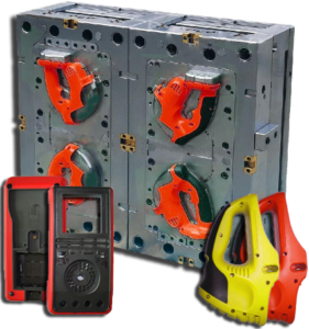
Break down and examine the plan of the ejector framework for the PC bezel comprising of 10 and 40 ejector pins of a similar breadth. The base pin widths are determined by the past model for the different number of ejector pins. The two plans give similar absolute edge around the ejectors thus additionally give a similar shear weight on the formed part. In the event that lone 10 pins are utilized, at that point the base pin measurement would be around 5.6 mm. Accepting consistently dispersed launch powers, the compressive anxieties in every one of the 10 pins would be 24 MPa. By examination, in the event that 40 pins are utilized, at that point the base width would be around 1.4 mm. The compressive pressure in every one of the 40 pins would be roughly 95 MPa. The plan for 10 uniformly divided, 5.6 mm ejector pins is appeared in in oem/odm automotives moulding factory. Since the doors are situated on the left and right side dividers, the ejector pins situated at the focal point of the top and base dividers would give required venting toward the finish of stream.

This plan, be that as it may, might be unsatisfactory for two reasons. To begin with, there may not be sufficient ejectors at areas close to where the embellishment will stick in the form. Specifically, the ribs and supervisors will in general therapist onto the center thus require close by ejector pins. Second, the ejector pin width is marginally huge given the closeness of the close by ribs. In this plan, just 1 mm of steel isolates the ejector opening from the outside of the shape cavity. With high liquefy pressures, stresses will create in the steel, misshaping the ejector openings to be nonround, causing the ejector pins to tie. In the long run, breaks will spread between the ejector opening and the shape hole. Consequently, the ejector pins should be made more modest and all the more deliberately found.

This article is from https://www.injectionmouldchina.com

Interlocking Core

At the point when the part math permits, slim centers with little breadths can be interlocked with the contradicting mold cavity as appeared in Fig. 9.25. Such a plan from injection moulding design china has two preferences. In the first place, the interlocking of the center with the depression offers help for the center and will in general decrease the center flexture as broke down in oem/odm industrial injection mold factory. Second, the interlocking gives a methods by which to pass on coolant from the moving side of the shape, through the center, and to the fixed side of the form. Air is ordinarily utilized as the coolant in such a plan since this coolant will be presented to the shaped part and the climate when the form is opened. While air has a low thickness, which lessens its cooling viability, plan with air channels will give considerably more warmth move than a strong center pin.

There are two regular embellishment circumstances in which there is irrelevant warmth stream from one side of the trim. The first is the long slim center indicated before in china injection mold factory, which depends exclusively on conduction down the hub of the slim pin to move heat from within the embellishment. Since the pin is so thin, there will be very lttle heat move down the length of the pin. Thus, most of the warmth must be moved to the cooling lines in the depression embed.

pom moulding parts made in china plots the warmth motion in a form having a thin center pin. The transition vectors demonstrate that there is some noteworthy warmth move around the centerline of the pin towards the coolant at its base. Nonetheless, the pin’s cross-sectional zone is little to the point that there is an overwhelming outspread warmth motion at the outside of the pin. All in all, the hot plastic liquefy that is contacting the center must exchange a large portion of its warmth entirely through the plastic to the metal and cooling lines of the depression embeds.

As to the cooling of such slim centers, the form creator ought to comprehend that the cooling time will probably be stretched out because of the restricted warmth move to the coolant. A most dire outcome imaginable can be promptly examined by expecting that there is no warmth ransfer deeply. The warmth fIux in this situation is appeared in china high precision mold manufacturer. Since all the warmth must exchange through one side of the trim, the warm conduct is basically equivalent to if two layers of the plastic dissolve were on head of one another. This twofold thickness portrayal is legitimate since the temperature circulation is symmetric over the centerline so there is no related warmth motion.

Uneven warmth stream will likewise happen when forming a plastic layer on head of another material that is ineffectively conductive, as in two-shot (multishot) shaping or overmolding, In these cycles, the primary layer or item may go about as a cover that restricts the warmth stream from the polymer liquefy just injected. As in china mold component machining, the impact of the protecting layer is to confine the warmth stream to only one side of the polymer liquefy. To ascertain the warmth move rates for such uneven warmth streams, mold manufacturing factory might be utilized by subbing double the genuine thickness of the embellishment for the thickness variable, h. The net outcome is that any trim application with an uneven warmth stream will have roughly a four-overlap increment in the cooling time over an embellishment cooled from different sides.

This article is from https://www.injectionmouldchina.com

Different Parts Influence the Mold Costs

There are numerous reasons that formed parts are dismissed in the high precision mold factory. Injection molds factory has good QC and some normal imperfections incorporate short shot, streak, defilement, ill-advised shading match, surface striations because of spread or redden, warpage and other dimensional issues, consume marks, helpless gleam, and others. Since clients request top notch levels on the formed parts they buy, disintegrates frequently inside review and eliminate any inadequate parts that are shaped before shipment to the client.

The expense of these imperfections in the china tooling-building manufacturers can be consolidated into the part cost by assessing the yield. Regular yields fluctuate from 50 to 60 % at fire up for a troublesome application with numerous quality prerequisites to basically 100% for a completely developed ware item. Many cost assessment techniques have been created for formed plastic parts with changing degrees of causality and exactness. The accompanying cost assessment technique of china precision molds manufacturers was created to incorporate the fundamental impacts of the part structure and embellishment measure while being moderately easy to utilize.

A form base is a format or clear shape that is fit to be modified. Alluding to the form plan, the shape base incorporates most of the shape except for the center supplement, cavity embed, hot sprinter, and related parts, for example, ejector pins, uphold columns, and cooling plugs.

The expense of the shape base is a component of the mass of the form and the expense of the steel per unit mass. Measurable cost investigation of shape bases was led and discovered that cost could be firmly demonstrated as where Mmold is the mass of the form base in kg, and Kmold material compares to the expense of the form material per kilogram. Cost information for some generally utilized materials is given. The coefficients were determined by factual relapse of genuine shape base expenses for a few distinctive form bases (from little to enormous size) and four standard form base materials. The gave model has a coefficient of assurance, R2, of 0.922 across 24 distinctive form base statements and gives sensible quotes of the shape base.

Given the different shape measurements, the mass of the form base was assessed factually from relapse of eight diversely measured form bases as While the form measurements are concluded during the shape format configuration measure, they can be at first assessed as where Neavies length and neavitie width are the quantity of holes over the length and width measurements. The factor of 1 .33 is incorporated to accommodate a recompense around the form pits. On the off chance that the format of the shape depressions over the shape is obscure, a lattice design is at first accepted as where the capacity roof adjusts any noninteger number up to the following whole number.

This gauge will in general cause the shape to have bigger size and cost than would really be acknowledged, yet will give in any event a sensible gauge.

The expense of the center and pit embeds is ordinarily the single biggest driver of the all out shape cost. The purposes behind their cost are that they have to contain each mathematical detail of the formed part, are made of extremely hard materials, and are done to a serious extent of precision and quality.

The complete expense of all the hole and center supplements is driven by the expense of each arrangement of additions, Cawitv, increased by the quantity of pit sets, Nnaities, and a markdown factor,favity dscomt, which diminishes the expense per depression with the quantity of cavities.

This article is from https://www.injectionmouldchina.com/.