Mold Layout Design

When the heap cases are created for superposition, the recently introduced pressure and bowing examinations might be performed to gauge the pressure in the help column, σ, the avoidance because of pressure, oppression; and the redirection because of bowing, bending. The avoidance across the outside of the mold hole can be assessed as an element of the distance, x, from the centerline of the help column. Where L is the length of the range from the help column to the ejector rail and the scope of x is confined to one a large portion of the length of the range.

The greatest avoidance of the mold will happen either at the focal point of the help column or somewhere between the help column and the ejector rail, contingent upon the general sizes of the redirections. This prompts the accompanying equation for the most extreme avoidance given the superimposed pressure and twisting.

The mold creator ought to consistently consider the conveyance of the powers applied by the polymer liquefy in the cavity to decide the area and size of the help columns. Consistently dispersed help columns might be adequate, yet are once in a while ideal, Often, it is valuable for high-precision mould manufactory to break down the mold into discrete regions for primary investigation and plan.
injection mold gate design

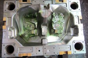
The underlying conduct of every 50% of the mold for eight depressions could be examined with a range of 359 mm and a width of 178 mm. The foundational layout may incorporate two huge help columns under each gathering of four cavities as appeared at left, or six more modest help columns separated between sets of depressions as appeared at right. The mold fashioner could likewise consider one help column straightforwardly under every pit. Every one of these plans can be examined. The last plan will be resolved by the underlying exhibition, yet in addition the discharge and upkeep contemplation. Once more, the easiest and most conservative plan is generally liked.

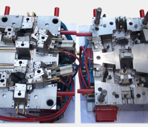
The mold format plan of oem injection mold factory is remarkable for two different reasons. In the first place, this plan shows 16 center additions pressed straightforwardly in a 4×4 matrix in one enormous pocket in the center plate with no interceding mold steel. This plan is substantially more smaller and less expensive to deliver than a plan with 16 individual pockets for the center supplements. Be that as it may, the plan will require cautious machining, completing, and get together of the mold embeds since resilience issues can cause positional mistakes and issues during trim, for example, coolant spills, blazing at the splitting line, or out of resistance molded parts. Second, the plan of china precision molds factory is a family mold in which each set of eight holes is molded with various thicknesses and at various liquefy pressures. Planning the hot sprinter feed framework would be testing. A stacked “X” type complex like the plan of plastic injection molding services china could be utilized with various measurements for the essential sprinters to adjust the dissolve pressures during filling.

Be that as it may, given the distinctive part thicknesses and comparative pressing weights gave to all the holes, the mold originator ought to anticipate less shrinkage in the more slender top moldings and specified a lower shrinkage esteem as needs be.

The portrayed investigation techniques give sensible direction to mold plan. On the other hand, primary recreations of injection mould manufacturers utilizing limited component investigation can be performed utilizing the point by point mold math. Such primary examination procedures are getting progressively coordinated with PC stream recreations to give high-devotion forecasts while likewise decreasing huge hindrances to routine usage.

This article is from https://www.injectionmouldchina.com
Mold Plates Compression and Bending

Most of the mold comprises of plates, including the top clasp plate, A plate, cavity embeds, center additions, B plate, uphold plate, ejector plate, ejector retainer plate, and the back clip plate. A prominent exemption is the plan of molds with profound centers, wherein the center supplement isn’t built from a plate yet rather from a pole; this sort of form configuration has a different arrangement of issues that are along these lines examined by china high precision injection molding machine.

Every one of the mold plates is regularly exposed to a heap on one face of the plate. While the sides of the plate might be obliged by encompassing plates, most of the applied burden is conveyed by compressive and shear stresses and consequently sent through the thickness and across the plate. Plate pressure and bowing are next independently examined.

In the event that the plate is completely upheld by basic mold plates and the form platen (as common on the fixed side of the form), at that point all plates are in pressure and there is irrelevant plate twisting. It ought to be noticed that compressive powers because of mold bracing will in general reason uniform compressive burdens through the form plates. The compressive pressure, σ, is characterized as the power, F, per unit of compacted territory, Acompression: σ=F/Acompression The strain, e, that creates is the pressure isolated by the versatile modulus, E: e=σ/E

Diversion because of pressure isn’t generally an issue since 1) it is moderately little and 2) it is uniform across the form. In that capacity, it doesn’t ordinarily cause blazing or huge dimensional change in the chinese mold component machining manufacturers. As the accompanying model will show, in any case, the mold planner ought to marginally expand the profundity of the form pit to make up for plate pressure if a tight resistance is determined on the thickness of a section with a profound hole.

In the event that the back essence of the plate isn’t completely upheld, at that point shear stresses will create and Cause the plate to twist, Plate bowing is a normal issue for the plates situated between the ejector lodging and the form depression 0n the moving side of the mold. The shear pressure, T, is characterized as the power, F, per unit of zone in shear, Ashear: T=F/Ashear

China high precision mold manufacturer  Guangzhou Klarm Mould Limited gives an illustration of a static power examination of a part of the bezel form that is in shear, While the genuine shear stresses will shift with the appropriation of the liquefy pressure across the mold depression, a sensible gauge can be accomplished by expecting a uniform circulation around the border of the mold hole. In that capacity, the region in shear is: The key issue with plate twisting in mold configuration isn’t the presence of shear stresses in the plates, yet rather the improvement of enormous redirections across any long unsupported ranges of the form plates. Most mold use a moving ejector get together, thus don’t completely uphold the help plate between rails of the ejector lodging. Likewise, the mold plates act like a pillar in bowing. The glorified case is spoken to in china molds produce services in which the whole burden, F, is thought to be applied to the focal point of the mold area. This supposition that is made to give a traditionalist gauge of the most extreme redirection.

As for different depression mold, the examination ought to be applied to isolate bits of the form cavity as suitable. china injection mold factory gives a top and side perspective on a format plan for a six-pit mold. One investigation approach is to lump the liquefy pressure across three holes together to register the applied power, F, which acts fundamentally on the compelling width, W. It ought to likewise be noticed that the powerful plate thickness, H, ought exclude the thickness of the centers when the centers don’t contribute altogether to the solidness of the form get together.

This article is from https://www.injectionmouldchina.com
Reverse Ejection

The depression embeds in many molds are situated inside the fixed side of the form and the center additions are situated on the moving side of the shape. Since the formed part contracts onto the centers as the plastic cools, the shaped parts will in general stay with the centers on the moving side of the form when the shape is opened.

Appropriately, molds are normally planned with an ejector lodging and ejector plate on the moving side of the shape to such an extent that ejector pins can eliminate the part from the center. In any case, this ordinary plan from china high precision mold manufacturer is tricky in that it doesn’t accommodate a simply stylish surface, totally liberated from abandons, on one or the other side of the formed part. Witness imprints will ordinarily be left on the center side of the formed part from the ejector pins while witness imprints will commonly be left on the depression side of the shaped part from the feed framework.

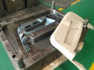
To give a totally tasteful surface, molds can be planned with “switch launch.” One such plan is appeared in oem/odm automotives molding factory, which incorporates a form hole plate 68 on the moving side of the shape and a form center plate 38 on the fixed side of the shape 36. The sprue 76 passes on the plastic liquefy from the machine spout 14 through the shape center plate 38 to the form cavity 40 and 74. Since the shaped part will in general stay on the form center, the fixed side of the form 36 likewise incorporates ejector pins 48 and different segments that work with an ejector plate 30 situated between rails 18. Since the trim machine’s ejector pole is situated on the moving side of the embellishment machine and is futile with this shape plan, the form configuration likewise incorporates water driven chambers 32 for incitation of the ejector plate. Because of this shape plan, the whole surface of the formed part inverse the center is liberated from restorative imperfections.

There are points of interest and inconveniences of the shape plan of oem/odm industrial injection mold factory contrasted with the past plan of china mold component machining. The essential preferred position is the utilization of various equipping stages to decouple the incitation of the rack and pinion from the turn of the centers. All things considered, it is conceivable to defer and in any case program the pivot of the centers during the form opening while at the same time evading the exceptionally huge stack stature related with the coarse helix of the past plan. The essential burden is the enormous number, complex design, and huge volume of the outfitting stages. Furthermore, the planetary design proposes an outspread format of pits thus may require extremely enormous molds for a high number of holes. Appropriately, the planetary stuff configuration might be ideal in a shape with a moderately low number of cavities requiring high incitation forces.

This article is from https://www.injectionmouldchina.com/

Collapsible Core

Split pit molds are frequently utilized when the part configuration incorporates complex and undermining outer surfaces. Folding centers are regularly utilized when the part configuration incorporates complex and undermining surfaces on the inside of the part. The plan of a shape which incorporates a folding center is appeared in high precision mould china, which was created to form the top of a doll with an almost uniform divider thickness [12]. The shape depression (14 and 15 together) is framed by two hole embeds 12 and 13, which are burrowed out by a folding center 17. In this plan of automotive mould made in china, the folding center is contained eight sections: 18, 19, 20, 21, 22, 23, 24, and 25. Four of the fragments 18, 19, 20, and 21 are generally three-sided in area and fitted at the corners with a molded external surface in the ideal type of the center. The other four portions 22, 23, 24, and 25 are generally planar in segment and fitted between the corner sections with a shaped external surface to finish the ideal type of the center.

A center pole 37 is situated at the focal point of the center, and forestalls the outspread uprooting of the eight fragments when the folding center is collected. To forestall the pivotal dislodging of the folding center, every one of the eight fragments have a stem 35 with outside strings 35a that draw in the inward strings 39 out of a sleeve 38.

The activity of the folding center depends upon the strings 37b of the center pole 37, and their commitment with the strung way 41 of the sleeve 38. In particular, preceding trim the center bar is turned inside the sleeve so it completely reaches out until its distal (far) end is flush with the finishes of the eight fragments to shape an inflexible center 17. The sleeve with the inflexible center is then positioned in the form cavity and the part is shaped by traditional practice. When the part is hardened, the shape is opened and the formed part is eliminated alongside the center and sleeve. The center pole 37 is then unscrewed from sleeve 38 and eliminated from within the center 17. With no help, the eight portions can implode and be eliminated from within the formed part. The fragments, center bar, and sleeve are then reassembled for the following embellishment cycle.

The folding center plan of oem/odm automotives moulding factory permits complex and undermining highlights to be shaped inside to the formed part. On account of its plan, notwithstanding, a lot of time is needed to collect and dismantle the moving center. To encourage the plan and assembling of molds with folding centers, standard folding center plans have been created and are accessible from various shape base and segment providers. In common plans, the activation of the ejector plate slides the portions along a holding sleeve, which gives a cam activity to implode the center sections during the discharge of the shaped part. This article is from https://www.injectionmouldchina.com/