Mold Plates Compression and Bending

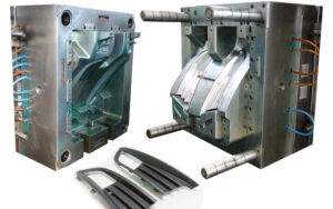
Most of the mold comprises of plates, including the top clasp plate, A plate, cavity embeds, center additions, B plate, uphold plate, ejector plate, ejector retainer plate, and the back clip plate. A prominent exemption is the plan of molds with profound centers, wherein the center supplement isn’t built from a plate yet rather from a pole; this sort of form configuration has a different arrangement of issues that are along these lines examined by china high precision injection molding machine.

Every one of the mold plates is regularly exposed to a heap on one face of the plate. While the sides of the plate might be obliged by encompassing plates, most of the applied burden is conveyed by compressive and shear stresses and consequently sent through the thickness and across the plate. Plate pressure and bowing are next independently examined.

In the event that the plate is completely upheld by basic mold plates and the form platen (as common on the fixed side of the form), at that point all plates are in pressure and there is irrelevant plate twisting. It ought to be noticed that compressive powers because of mold bracing will in general reason uniform compressive burdens through the form plates. The compressive pressure, σ, is characterized as the power, F, per unit of compacted territory, Acompression: σ=F/Acompression The strain, e, that creates is the pressure isolated by the versatile modulus, E: e=σ/E

Diversion because of pressure isn’t generally an issue since 1) it is moderately little and 2) it is uniform across the form. In that capacity, it doesn’t ordinarily cause blazing or huge dimensional change in the chinese mold component machining manufacturers. As the accompanying model will show, in any case, the mold planner ought to marginally expand the profundity of the form pit to make up for plate pressure if a tight resistance is determined on the thickness of a section with a profound hole.

In the event that the back essence of the plate isn’t completely upheld, at that point shear stresses will create and Cause the plate to twist, Plate bowing is a normal issue for the plates situated between the ejector lodging and the form depression 0n the moving side of the mold. The shear pressure, T, is characterized as the power, F, per unit of zone in shear, Ashear: T=F/Ashear

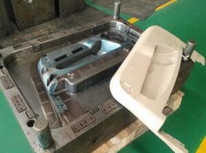
China high precision mold manufacturer  Guangzhou Klarm Mould Limited gives an illustration of a static power examination of a part of the bezel form that is in shear, While the genuine shear stresses will shift with the appropriation of the liquefy pressure across the mold depression, a sensible gauge can be accomplished by expecting a uniform circulation around the border of the mold hole. In that capacity, the region in shear is: The key issue with plate twisting in mold configuration isn’t the presence of shear stresses in the plates, yet rather the improvement of enormous redirections across any long unsupported ranges of the form plates. Most mold use a moving ejector get together, thus don’t completely uphold the help plate between rails of the ejector lodging. Likewise, the mold plates act like a pillar in bowing. The glorified case is spoken to in china molds produce services in which the whole burden, F, is thought to be applied to the focal point of the mold area. This supposition that is made to give a traditionalist gauge of the most extreme redirection.

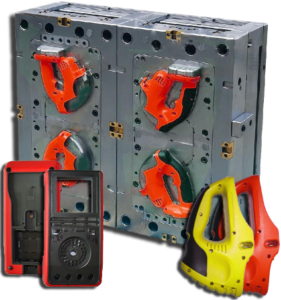
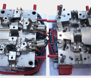
As for different depression mold, the examination ought to be applied to isolate bits of the form cavity as suitable. china injection mold factory gives a top and side perspective on a format plan for a six-pit mold. One investigation approach is to lump the liquefy pressure across three holes together to register the applied power, F, which acts fundamentally on the compelling width, W. It ought to likewise be noticed that the powerful plate thickness, H, ought exclude the thickness of the centers when the centers don’t contribute altogether to the solidness of the form get together.

This article is from https://www.injectionmouldchina.com

Reverse Ejection

The depression embeds in many molds are situated inside the fixed side of the form and the center additions are situated on the moving side of the shape. Since the formed part contracts onto the centers as the plastic cools, the shaped parts will in general stay with the centers on the moving side of the form when the shape is opened.

Appropriately, molds are normally planned with an ejector lodging and ejector plate on the moving side of the shape to such an extent that ejector pins can eliminate the part from the center. In any case, this ordinary plan from china high precision mold manufacturer is tricky in that it doesn’t accommodate a simply stylish surface, totally liberated from abandons, on one or the other side of the formed part. Witness imprints will ordinarily be left on the center side of the formed part from the ejector pins while witness imprints will commonly be left on the depression side of the shaped part from the feed framework.

To give a totally tasteful surface, molds can be planned with “switch launch.” One such plan is appeared in oem/odm automotives molding factory, which incorporates a form hole plate 68 on the moving side of the shape and a form center plate 38 on the fixed side of the shape 36. The sprue 76 passes on the plastic liquefy from the machine spout 14 through the shape center plate 38 to the form cavity 40 and 74. Since the shaped part will in general stay on the form center, the fixed side of the form 36 likewise incorporates ejector pins 48 and different segments that work with an ejector plate 30 situated between rails 18. Since the trim machine’s ejector pole is situated on the moving side of the embellishment machine and is futile with this shape plan, the form configuration likewise incorporates water driven chambers 32 for incitation of the ejector plate. Because of this shape plan, the whole surface of the formed part inverse the center is liberated from restorative imperfections.

There are points of interest and inconveniences of the shape plan of oem/odm industrial injection mold factory contrasted with the past plan of china mold component machining. The essential preferred position is the utilization of various equipping stages to decouple the incitation of the rack and pinion from the turn of the centers. All things considered, it is conceivable to defer and in any case program the pivot of the centers during the form opening while at the same time evading the exceptionally huge stack stature related with the coarse helix of the past plan. The essential burden is the enormous number, complex design, and huge volume of the outfitting stages. Furthermore, the planetary design proposes an outspread format of pits thus may require extremely enormous molds for a high number of holes. Appropriately, the planetary stuff configuration might be ideal in a shape with a moderately low number of cavities requiring high incitation forces.

This article is from https://www.injectionmouldchina.com/

Ejector

The utilization of a molded ejector pin configuration requires cautious ejector pin configuration just as cautious arrangement of the ejector pin to the part includes. Besides, there is a potential issue that can emerge with the utilization of formed ejectors stretching out external the splitting line of the shape pit as shown in oem/odm industrial injection mold factory. In particular, in the event that the ejector pin is too short, at that point a hole will shape between the highest point of the ejector pin and the contrary surface of the pit embed. In the event that this hole is bigger than the thickness of a vent, at that point streak is probably going to happen. In the interim, in the event that the ejector pin is too long, at that point the pin will meddle with the restricting plate and be packed upon shape conclusion. With rehashed discharge cycles, the pin can exhaustion and clasp. Given that the necessary length of the ejector pin is hard to definitely decide because of the stack-up in resistances over the form get together, the shape fashioner may wish to utilize a”steel-safe” approach with various length changes. Then again, the shape architect may decide to put the ejector pin inside the form cavity and shape the pin with respect to the rib in china mold component machining. In these cases, slight blunders in the shape of the pin will be on non-aesthetic surfaces as be less huge as for the nature of the embellishment.

After the number, format, and math of the ejectors have been resolved, the detailing of the plan should be finished to guarantee hearty shape gathering and activity, There are a few unmistakable issues that should be tended to. To start with, the form architect ought to perceive that the shape gathering is muddled by the enormous number of ejector framework segments that must be at the same time mated to the center supplements. This issue is compounded by resistance stack-up over various plates in the form gathering. Taken together, the shape gathering can devour a decent measure of time and result in harm of important form parts.

To encourage the form get together, cautious enumerating is required any place the ejector framework segments interface with different parts in the shape. mold manufacturing factory gives a top and area perspective on a round ejector pin (left) and a molded ejector pin (right). china automatives injection overmould manufacturers shows that a leeway can be given between the pin and the drag of the ejector opening to vent uprooted air during the embellishment cycle. The investigation of the vent’s leeway was given in china high precision mold manufacturer, demonstrating that commonly a freedom of 0.02 mm (0.001 in) is accommodated a sliding bearing length of the request for a few widths of the ejector pin. Past this bearing length, the ejector opening should venture to a bigger size So as to not confine the sliding of the pin. The size of the leeway isn’t basic yet rather just restricted by the impedance with other close by parts. A chamfer should be given from the bigger distance across to the bearing/venting breadth.

Something else, the ejector pin would will in general hang up on the sharp corner during mold get together, which can hamper the shape gathering when attempting to find a large number of ejector pins.

This article is from https://www.injectionmouldchina.com

Bubbler

Bubblers are a somewhat more modest option in contrast to perplexes with fundamentally the same as cooling execution. In this plan, appeared in precision molds factory, the coolant circles around the outside of the bubbler, and returns down within the bubbler. Contrasted with an astound, the bubbler doesn’t contact the center thus conveys no heap from the center pressure. Along these lines, the bubbler is planned with an extremely flimsy divider thickness and minimal measurements. Bubblers with a distance across of under 2 mm can be utilized by china plastic pipe fitting mould maker in bored openings under 3 mm in measurement. The essential disservice of bubblers is that they require two cooling channels- – one to give stream around the bubbler and one moment to restore the stream from inside the bubbler. Thusly, the advantage of the more modest opening measurement related with the bubbler accompanies a to some degree more prominent cost concerning its establishment.

A warmth pipe is a shut gadget with an inward hole that contains a liquid which bubbles at a temperature between the soften temperature and the coolant temperature. Hairlike activity makes the cooled inside liquid ascension the external dividers of the warmth pipe. At the point when set inside a form center as appeared in mould produce manufacturers, the expanded temperature along the length of the warmth pipe causes the liquid inside the warmth line to dissipate and re-visitation of the base of the warmth pipe where the gas cools and gathers. Due to this constant pattern of buildup and vanishing of the fluid inside the warmth pipe, moderately high cooling rates can be accomplished without requiring the progression of shape coolant along the pivot of the form center.

The warmth pipe has become a standard shape segment that is accessible from various providers. Their essential favorable circumstances incorporate little size, great warmth move rates, and simplicity of establishment. In any case, their cooling viability isn’t as high as that as bubblers or bewilders. The explanation is that the mass movement of the form coolant, which has a high explicit warmth and a much lower temperature than the soften temperature, gives an a lot higher pace of warmth move than that gave by heat pipes. Warmth pipes additionally have potential issues identified with their underlying reaction (since they require a huge temperature slope to start a compelling buildup vanishing cycle) just as their adequacy under an assortment of coolant and soften temperatures (identified with the math and material properties). For centers with little distances across, under 5 mm, it may not be conceivable to convect heat along the pivot of the center utilizing any of the recently referenced plans.

Accordingly, the main choice might be to use a conductive pin to encourage heat move as appeared in china high precision mold manufacturer. In this plan, form coolant streams around the rear of the pin to move however much warmth as could reasonably be expected from the pin. With high length to breadth proportions, be that as it may, the warmth move isn’t powerful. In such cases, the center pins forestall the progression of warmth down the length of the center pins and act fundamentally as encasings.

This article is from https://www.injectionmouldchina.com

Interlocking Core

At the point when the part math permits, slim centers with little breadths can be interlocked with the contradicting mold cavity as appeared in Fig. 9.25. Such a plan from injection moulding design china has two preferences. In the first place, the interlocking of the center with the depression offers help for the center and will in general decrease the center flexture as broke down in oem/odm industrial injection mold factory. Second, the interlocking gives a methods by which to pass on coolant from the moving side of the shape, through the center, and to the fixed side of the form. Air is ordinarily utilized as the coolant in such a plan since this coolant will be presented to the shaped part and the climate when the form is opened. While air has a low thickness, which lessens its cooling viability, plan with air channels will give considerably more warmth move than a strong center pin.

There are two regular embellishment circumstances in which there is irrelevant warmth stream from one side of the trim. The first is the long slim center indicated before in china injection mold factory, which depends exclusively on conduction down the hub of the slim pin to move heat from within the embellishment. Since the pin is so thin, there will be very lttle heat move down the length of the pin. Thus, most of the warmth must be moved to the cooling lines in the depression embed.

pom moulding parts made in china plots the warmth motion in a form having a thin center pin. The transition vectors demonstrate that there is some noteworthy warmth move around the centerline of the pin towards the coolant at its base. Nonetheless, the pin’s cross-sectional zone is little to the point that there is an overwhelming outspread warmth motion at the outside of the pin. All in all, the hot plastic liquefy that is contacting the center must exchange a large portion of its warmth entirely through the plastic to the metal and cooling lines of the depression embeds.

As to the cooling of such slim centers, the form creator ought to comprehend that the cooling time will probably be stretched out because of the restricted warmth move to the coolant. A most dire outcome imaginable can be promptly examined by expecting that there is no warmth ransfer deeply. The warmth fIux in this situation is appeared in china high precision mold manufacturer. Since all the warmth must exchange through one side of the trim, the warm conduct is basically equivalent to if two layers of the plastic dissolve were on head of one another. This twofold thickness portrayal is legitimate since the temperature circulation is symmetric over the centerline so there is no related warmth motion.

Uneven warmth stream will likewise happen when forming a plastic layer on head of another material that is ineffectively conductive, as in two-shot (multishot) shaping or overmolding, In these cycles, the primary layer or item may go about as a cover that restricts the warmth stream from the polymer liquefy just injected. As in china mold component machining, the impact of the protecting layer is to confine the warmth stream to only one side of the polymer liquefy. To ascertain the warmth move rates for such uneven warmth streams, mold manufacturing factory might be utilized by subbing double the genuine thickness of the embellishment for the thickness variable, h. The net outcome is that any trim application with an uneven warmth stream will have roughly a four-overlap increment in the cooling time over an embellishment cooled from different sides.

This article is from https://www.injectionmouldchina.com

Thermal Gate

The utilization of a hot runner feed system by china molds produce services wipes out the requirement for the embellishment and cooling of a chilly runner. The plan of gates for hot runners  fluctuates considerably from those for cold runners. The essential targets are commonly the equivalent with respect to the shear rate, pressure drop, and tasteful necessities. Notwithstanding, warm entryways in hot runners should likewise give a set attachment that forestalls the condensed plastic dissolve in the hot runner from streaming out of the gate when the shape opens and the set plastic close to the gate is taken out with the embellishment.

One of the most common sorts of gates utilized by china high precision mold manufacturer in hot runners is the pin-point warm entryway framed with an internal”torpedo” .In this plan, a profoundly conductive torpedo is embedded into the spout close to the entryway. The motivation behind the torpedo is to communicate heat from the spout towards the entryway and keep the plastic liquid inside. Normally, at least two holes in the torpedo are utilized to pass on the plastic dissolve in the feed system into the depression. A slender layer of remaining plastic liquefy is utilized to protect the hot torpedo from the virus form dividers.

During the filling stage in precision molds factory, the liquefy pressure from the trim machine increments until the weight inside the torpedo powers any cemented plastic between the torpedo holes and the entryway into the form pit. The soften would then be able to spill out of the hot runner spout, through the openings, and into the form depression much like a customary cold runner feed system. At the point when the stream stops, the warmth move to the shape will make the protecting plastic mostly set, with the plastic around the tip of the torpedo getting hardened. At the point when the form opens, a little annulus of the cemented material will be broken around the torpedo tip. Nonetheless, a slight hardened layer will remain that keeps the spillage of the dissolve from the hot runner to the earth.

The warm pin-point entryway is an astute plan as for its double utilization of the plastic to decrease heat move and structure a strong seal. In any case, it has three critical drawbacks. To begin with, pin-point gates ordinarily have a little entryway measurement. Similarly likewise with traditional pin-point entryways for cold runners, the distance across of the warm gate and its related holes must be intended to give sensible weight drops and shear rates. On account of the little holes, this gate configuration may not be appropriate for shear touchy 0r vigorously filled materials. The subsequent burden is identified with the home of the protecting plastic. After some time, any stale material will corrupt with the possibility to be maneuvered into the stream and pollute the plastic soften, most ordinarily as dark bits in the formed parts.

The habitation of the protecting plastic can likewise cause huge issues when the decay plays out a shading change, since even limited quantities of leftover material may cause shading streaking on hence formed parts. A third weakness of the warm entryway may likewise emerge. Specilically, the set layer must be constrained from the entryway by expanded liquefy pressure toward the beginning of the trim cycle. The size and timing of the liquefy weight may shift marginally from gate to entryway contingent upon entryway resistances, entryway gathering, and gate temperature dissemination.While not an issue in most trim applications, these differences might be risky in accuracy forming applications.

This article is from https://www.injectionmouldchina.com