Ejector

The utilization of a molded ejector pin configuration requires cautious ejector pin configuration just as cautious arrangement of the ejector pin to the part includes. Besides, there is a potential issue that can emerge with the utilization of formed ejectors stretching out external the splitting line of the shape pit as shown in oem/odm industrial injection mold factory. In particular, in the event that the ejector pin is too short, at that point a hole will shape between the highest point of the ejector pin and the contrary surface of the pit embed. In the event that this hole is bigger than the thickness of a vent, at that point streak is probably going to happen. In the interim, in the event that the ejector pin is too long, at that point the pin will meddle with the restricting plate and be packed upon shape conclusion. With rehashed discharge cycles, the pin can exhaustion and clasp. Given that the necessary length of the ejector pin is hard to definitely decide because of the stack-up in resistances over the form get together, the shape fashioner may wish to utilize a”steel-safe” approach with various length changes. Then again, the shape architect may decide to put the ejector pin inside the form cavity and shape the pin with respect to the rib in china mold component machining. In these cases, slight blunders in the shape of the pin will be on non-aesthetic surfaces as be less huge as for the nature of the embellishment.

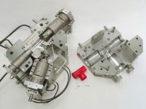
After the number, format, and math of the ejectors have been resolved, the detailing of the plan should be finished to guarantee hearty shape gathering and activity, There are a few unmistakable issues that should be tended to. To start with, the form architect ought to perceive that the shape gathering is muddled by the enormous number of ejector framework segments that must be at the same time mated to the center supplements. This issue is compounded by resistance stack-up over various plates in the form gathering. Taken together, the shape gathering can devour a decent measure of time and result in harm of important form parts.

To encourage the form get together, cautious enumerating is required any place the ejector framework segments interface with different parts in the shape. mold manufacturing factory gives a top and area perspective on a round ejector pin (left) and a molded ejector pin (right). china automatives injection overmould manufacturers shows that a leeway can be given between the pin and the drag of the ejector opening to vent uprooted air during the embellishment cycle. The investigation of the vent’s leeway was given in china high precision mold manufacturer, demonstrating that commonly a freedom of 0.02 mm (0.001 in) is accommodated a sliding bearing length of the request for a few widths of the ejector pin. Past this bearing length, the ejector opening should venture to a bigger size So as to not confine the sliding of the pin. The size of the leeway isn’t basic yet rather just restricted by the impedance with other close by parts. A chamfer should be given from the bigger distance across to the bearing/venting breadth.

Something else, the ejector pin would will in general hang up on the sharp corner during mold get together, which can hamper the shape gathering when attempting to find a large number of ejector pins.

This article is from https://www.injectionmouldchina.com

Ejection Force

When the necessary push territory and edge of the ejectors are known, distinctive ejector frameworks plans can be created. The form creator ought to think about various plans with a differing number and sizes of ejectors. There are preferences and hindrances to ejector framework plan methodologies having an enormous amount of little ejector pins contrasted with having less yet bigger ejector pins. As for tooling and activity costs, fewer huge ejector pins are liked by chinese mold component machining manufacturers.

There are two essential reasons. Initial, fewer ejectors requires a lower number of form segments and highlights to be machined. Consequently, the shape is more affordable to produce and keep up. Then, the bigger size of the ejectors will in general have exceptionally low compressive burdens and in this way be less defenseless to clasping.

Concerning plan flexibility and form activity, notwithstanding, a bigger number of little ejector pins is liked in high precision mold factory. There are a few reasons. To start with, the more noteworthy number of ejector pins considers more regular position of the ejectors over the pit.

This higher thickness of ejectors will in general accommodate more uniform venting and discharge. Simultaneously, more modest estimated ejectors permit more noteworthy plan adaptability as for the position of the ejectors. As recently talked about, molds contain numerous firmly dispersed and complex highlights so little ejector sizes permits pins to be viably positioned between cooling lines, down thin centers, on side dividers or ribs, and so forth

The mold planner from china precision molds manufacturers ought to recall that the above examination just gives a lower cutoff to the number and size of the ejectors. The shape architect can generally add ejectors or increment the ejector size to improve the consistency of discharge or lessen pressure in the formed part. The shape planner should likewise decide the sort of ejector to be utilized at different areas. Normal parts incorporate ejector pins, ejector edges, ejector sleeves, stripper plates, slides, lifters, point pins, center pulls, folding centers, expandable cavities, part hole molds, and others. The determination of the most fitting segments is vigorously subject to the prerequisites and math of the application. Therefore, the utilization of every one of these segments will be accordingly examined in china mould manufacturer.

Break down and examine the plan of the ejector framework for the PC bezel comprising of 10 and 40 ejector pins of a similar breadth. The base pin widths are determined by the past model for the different number of ejector pins. The two plans give similar absolute edge around the ejectors thus additionally give a similar shear weight on the formed part. In the event that lone 10 pins are utilized, at that point the base pin measurement would be around 5.6 mm. Accepting consistently dispersed launch powers, the compressive anxieties in every one of the 10 pins would be 24 MPa. By examination, in the event that 40 pins are utilized, at that point the base width would be around 1.4 mm. The compressive pressure in every one of the 40 pins would be roughly 95 MPa. The plan for 10 uniformly divided, 5.6 mm ejector pins is appeared in in oem/odm automotives moulding factory. Since the doors are situated on the left and right side dividers, the ejector pins situated at the focal point of the top and base dividers would give required venting toward the finish of stream.

This plan, be that as it may, might be unsatisfactory for two reasons. To begin with, there may not be sufficient ejectors at areas close to where the embellishment will stick in the form. Specifically, the ribs and supervisors will in general therapist onto the center thus require close by ejector pins. Second, the ejector pin width is marginally huge given the closeness of the close by ribs. In this plan, just 1 mm of steel isolates the ejector opening from the outside of the shape cavity. With high liquefy pressures, stresses will create in the steel, misshaping the ejector openings to be nonround, causing the ejector pins to tie. In the long run, breaks will spread between the ejector opening and the shape hole. Consequently, the ejector pins should be made more modest and all the more deliberately found.

This article is from https://www.injectionmouldchina.com

Ejection Forces

As depicted in china precision molds manufacturers, the item math and direction in the shape decides the number and area of the form’s splitting surfaces. In the event that the shape has no undermines or exceptional prerequisites, at that point just one splitting surface might be essential. In any case, in the event that the shape has inward or outer undermines, at that point extra splitting surfaces might be vital alongside the related discharge segments to impel the sliding cavity or potentially center additions to deliver the caught territories of the moldings so they might be catapulted. Such”split hole molds” are talked about in high precision mold factory.

The launch power, Feject, needed to eliminate a trim from a form center is an element of the typical power between the outside of the embellishment and the outside of the shape, Fnormal, along with the related draft point, φ, and the coefficient of static erosion, μs, between the formed part and the center addition. To appraise the discharge power, the contact power, Friction, is first figured as:

F friction=μs. Fnormal

The launch power is then determined as the segment of the rubbing power that is typical to the splitting surface:

Feject= cos(φ).Ffriction=μs .Cos(φ). Fnormal

The connections between these powers are spoken to in oem/odm automotives moulding factory. As the draft point diminishes from zero in Eq.11.2, the launch powers decline with the cosine of the draft point. The typical power acting between the formed part and the center is driven by the inside tractable anxieties in the plastic, which will make the plastic trim embrace the center like a versatile band. The ordinary power is assessed as the necessary of the lingering stresses, σ, in the formed part over the territory of the shaped part.

Estimated values for the coefficient of grinding shift from 0.3 for profoundly cleaned surfaces (with low surface unpleasantness) to more than 1.0 for harsh as well as finished surfaces [2]. Table 11.1 gives some coefficient of grating information produced by ASTM D 1894, Standard Test Method for Static and Kinetic Coefficients of Friction of Plastic Film and Sheeting. Prominently, grating materials, for example, filled PA6 have a higher coefficient of grinding. Surface completion is significant. In Table 11.1, LaserForm ST-100 alludes to a powdered, polymer-covered treated steel material that is molded into a green part with a laser and in this way sintered and penetrated with bronze to frame a thick, solid part with a 0.2 pμm surface harshness [3]. SL5170 is a fluid pitch material framed into a three-dimensional shape embed utilizing a stereolithography or polyjet measure with a surface unpleasantness of 3.6 pμm.

The obvious coefficient of erosion increments with surface harshness. The extremely high coefficient of rubbing equivalent to 5.47 among HDPE and SL5170 is accepted to be brought about by atomic bond [3].

The assessment of the remaining malleable burdens is an intricate capacity of the preparing conditions, form calculation, and material properties. A point by point treatment is well past the extent of china precision molds factory; chinese mold component machining manufacturers gives a decent proposal on the subject, and current PC reproductions can likewise give assessments of discharge powers [5, 6]. With the end goal of shape plan, traditionalist disentangling presumptions are applied to give a gauge of the launch power. The essential supposition that will be that the elastic anxieties in the embellishment are the aftereffect of the warm withdrawal of the cementing polymer inside shape. This presumption will make the examination over foresee the discharge powers since practically speaking the polymer (1) might be in a compressive state before the utilization of warm shrinkage, and (2) may will in general unwind. This article is from https://www.injectionmouldchina.com

Plastic Molding Distortion

The initial phase in the discharge of the moldings from the mold is to open the shape at least one splitting planes. The mold fashioner should work with the item planner and decay to guarantee that the shape configuration is appropriate and powerful. When all is said in done, the quantity of moving centers ought to be limited by improving the item plan and building up an appropriate shape plan. When moving centers are utilized by china molds design services, they should be planned, whenever the situation allows, to work with the initial activity of the form as opposed to depending on extra actuators and control frameworks.

Now and again the formed part requires a moving center plan that can’t be impelled by the shape opening development. Most current trim machines uphold such”core pull” groupings using advanced signs. After the cooling and plastication stages, when the shape is prepared to open, the trim machine can be customized to give at least one center draw signs to the necessary actuators (commonly pneumatic valves, water driven valves, electric solenoids, or electric engines). The actuators would then be able to withdraw the associated shape parts, which ought to be intended to contact a cutoff switch when completely withdrawn to give a positive input signal that the moving centers are withdrawn and the form is sheltered to open.

The trim machine will normally be modified to postpone the shape opening until all cutoff changes from all center force circuits are stimulated.

For china high precision mold supplier to eliminate the moldings from the shape, discharge powers must be applied to take the moldings off the center surfaces. These discharge powers can be applied by various shape segments including ejector pins, sleeves, sharp edges, lifters, air poppets, stripper plates, and different gadgets. The number, area, and plan of these segments must be created to dependably communicate the powers from the embellishment machine’s take out rod(s) through the launch framework to the plastic moldings. With each discharge cycle, huge shear and compressive powers are applied to the launch framework segments. On the off chance that the segments are inadequately planned, these launch powers may bring about exorbitant shear pressure, compressive pressure, selection, weariness, clasping, and shape disappointment. For instance, the 1se of too hardly any, little pins will cause such high shear stresses to in a real sense poke holes through the shaped section, an imperfection known as push-pin.

Similarly as the launch powers can cause pressure and diversion in the discharge framework segments, the launch powers can likewise cause pressure and redirection in the plastic moldings. To keep away from lasting twisting of the plastic moldings, the number, area, and plan of the ejector parts must be created to apply a low and uniform condition of pressure over the moldings. On the off chance that the ejector power is consistently conveyed across numerous focuses in the form hole, at that point the embellishment will be consistently ejected from the shape with no lasting mutilation.

this article is from https://www.injectionmouldchina.com

Warpage Sources

The above segments with respect to shrinkage relates to in-plane dimensional changes in the plastic moldings. At the point when moldings misshape or twist out of plane, at that point warpage is happening. In certain applications, the dimensional changes due to warpage can far surpass the shrinkage. Moreover, warpage can be as or more hard to foresee and address. While a thorough examination is outside the extent of this book, some useful direction is

While all warpage is because of differential shrinkage, the wellsprings of the differential shrinkage fluctuate. The most straightforward reason for differential shrinkage might be a temperature inclination through the divider thickness of the trim. This marvel is appeared in oem/odm automotives mold factory. In this shape plan, the cooling framework configuration is giving nonuniform cooling. The temperature of the formed part will be higher close to the center supplement than the cavity embed. The past cooling investigation of precision plastic injection mould factory, for instance, has indicated that a temperature contrast of 5°C between surfaces of the center and the pit embeds isn’t unprecedented.

Any temperature distinction through the thickness of the moldings makes an interpretation of legitimately to various shrinkage rates through the thickness too. The contrast between the shrinkage rate on the center surface and the shrinkage rate on the hole surface will cause a subsequent strain in the part as it cools. For the case of Fig. 10.18, the center surface is higher temperature thus this side of the plastic embellishment will encounter more noteworthy shrinkage after demolding. From statics, the range of ebb and flow, Rw warpage of the trim brought about by warpage can be determined by the condition: Rwarpage=2.h/(S center S pit )

where h is the divider thickness of the trim, and Score and S depression are the shrinkage paces of the embellishment adjoining the center and hole embeds as indicated by high precision plastic injection mould suppliers. Given the range of ebb and flow, the most extreme out of plane redirection at the edges of the trim, δ, can be assessed as around: δ= W.sin(W/Rwarpage ), where W is the good ways from the middle to the edge of the embellishment.

Temperature slopes through the divider thickness of the trim are one regular reason for warpage. Another critical reason for warpage is differential shrinkage because of temperature as well as weight inclinations over the region of the part. One ordinary model is appeared in high precision plastic making mould china. In this model, the liquefy pressure in the cavity can be a lot higher close to the entryway than at the limits of the form hole.

All things considered, the volumetric and straight shrinkage in the middle will be not exactly the shrinkage around the outside of the trim. In the event that the distinction in the shrinkage is sufficiently huge, at that point the focal point of the part will twist out of the plane delivering a “pipe shape.”

The differential shrinkage appeared in high precision molds made in china is like the differential shrinkage for the PC bezel appeared in quality control checks for injection moulding. Notwithstanding, Fig. 10.15 will in general twist because of differential shrinkage while the bezel appeared in quality control checks for injection moulding won’t. The explanation is that the window in the PC bezel precisely decouples the different sides from one another, with the end goal that each side is allowed to recoil freely. Warpage would likely possibly happen because of differential shrinkage over the part if the shrinkage rate on the left side was totally different from the shrinkage rate on the correct side, and correspondingly for differential shrinkage on the top side contrasted with the base side.

This article is from https://www.injectionmouldchina.com

Warpage Prediction

At the point when the embellishment comprises of a solitary shut zone, the material inside the trim is in constant contact with the end goal that any nonuniform shrinkage and stresses over the part may just be settled all through of plane twisting of the part. Injection mould manufacturers in china know that such warpage requires clasping of the plane of the part, which can happen when: (S edge一 S center)> 0.44. (h/W) (h/W)

where h is the divider thickness of the trim, and Scenter and Sedge are the shrinkage rates at the middle and edge of the part, and W is the good ways from the middle to the edge of the embellishment. This clasping examination models the embellishment as an isotropic roundabout plate under uniform outspread edge pressure with a clasping pressure limit of.

As the past warpage investigations have appeared, warpage is brought about by nonuniform shrinkage because of temperature inclinations through the divider thickness of the formed part, pressure angles over the territory of the shaped part, or temperature slopes aCross the zone of the shaped part. These are the most widely recognized reasons for warpage, and have been treated by high-precision mould china with the least complex conceivable examination. In any case, there are different reasons for nonuniform shrinkage including direction and remaining pressure. For additional data, the intrigued form fashioner is alluded to the examination writing.

Sensibly exact warpage forecasts may likewise be gotten with PC recreation as recently talked about. oem/odm largest plastic injection molding companies gives the warpage forecast from PC recreation for the reproduction portrayed for Fig. 10.8. The outcomes recommend that the center of the part will bow down while the left and right sides of the bezel will bow upwards. The purpose behind this conduct is the upper surface of the bezel contains more material, and this upper surface is contracting not exactly the lower part of the ribs.

Given that warpage can be huge contrasted with shrinkage, shape fashioners may decide to make up for warpage by invert biasing the form surfaces dependent on anticipated or noticed warpage. This predisposition is some of the time alluded to as “Kentucky windage,” a shooting term that alludes to the changes a separation shooter must make to represent the breeze [26]. In this manner, Kentucky windage in form configuration alludes to the shaping of the form cavity surfaces with the end goal that after twisting the formed part smoothes to the ideal shape. The utilization of such predisposition isn’t without discussion, since it acquires cost in the forming of shape cavity surfaces while likewise intrinsically changing the warpage and auxiliary conduct of the formed parts. Therefore, it stays a to some degree uncommon practice in oem/odm medical injection mold factory.

Break down warpage accepting that the cup top is focus gated and shaped with ABS at a pressing weight of 66 MPa at the focal point of the part and 0 MPa at the external edge. To assess the warpage, it is first important to compute the shrinkage rates and check the clasping basis. Given the 66 MPa pressing weight and a temperature of 132°C, the straight shrinkage at the middle will be 0.3 1% at the middle. At the edge, the weight of 0 MPa and temperature of 132°C gives a direct shrinkage of 1.66 %. Given that the cup is 2 mm in thickness and 81 mm in breadth, the clasping measure is expressed.

This article is from https://www.injectionmouldchina.com

Final Shrinkage

The disastrous the truth is that to china mould manufacturing manufacturers, the specific shrinkage won’t be known before the shape is planned, manufactured, and tried. The objective in the setting up the last shrinkage proposal

■to give a shrinkage esteem that is near the real shrinkage of the material,

■to furnish a form machined with a shrinkage esteem that might be worked under a scope of cycle conditions to bring the part measurements inside particular, and

■to give a form that is machined”steel safe” with the end goal that the shape can be promptly adjusted if important to bring the part inside determinations.

The introduced shrinkage investigation should give sensible shrinkage gauges given legitimate dissolve temperatures and soften pressures. In any case of plastic injection moulded components china, the assessed contract age can differ broadly given vulnerability about material properties and handling conditions. Therefore, the shrinkage investigation ought to be considered as supplementing different wellsprings of data about shrinkage, The shrinkage examination ought not be utilized in disconnection given the potential for blunder. Notwithstanding, the shrinkage examination ought to be utilized to confirm the shrinkage gauges coming from different sources.

There are a few normal wellsprings of shrinkage information that might be utilized (notwithstanding examination) to help  plastic injection mold manufacturers china with setting up the last shrinkage proposal. Most ordinarily, a material provider or other testing research center may shape parts in a standard test form to assess the shrinkage. Commonly, the test form comprises of a 2 or 3 mm thick plaque that is shaped at mid-range dissolve temperatures and weights. The formed parts are then permitted to equilibrate for quite a while before their measurements are estimated and the straight shrinkage determined. This shrinkage data, when accessible, is generally precise since the testing was led for the specific material of interest at conditions near most embellishment applications. In any case, the gave shrinkage information may not be exact if the divider thickness or handling states of the embellishment application differ essentially from that of the test shape.

One critical issue with shrinkage information from a material provider is that the shrinkage information may not be founded on testing of the genuine material by high-precision molds made in china, but instead suppositions that the material will carry on as evidently comparative materials that have been recently tried. A more costly however more precise option is to configuration, assemble, and test a model shape that has a stream length, divider thickness, and cooling framework like the particular embellishment application. Such model embellishment gives dissolve weights and temperatures that ought to be fundamentally the same as those of the last creation form, so the shrinkage saw with the model shape should be near the last production form. While the advancement of a model shape can be costly, the exactness of the shrinkage estimations can be helpful in close resilience applications.

Another choice is to depend on shrinkage information from past form plans and decay insight. Much of the time, molds may as of now have been planned and worked for creation of moldings that are fundamentally the same as the current form plan application. In such cases, the mold originator of injection molding service china may acquire the best gauges by contrasting the estimations of the moldings and those of the shape steel measurements.

Before making last proposals, in any case, the shape originator ought to ask with the decay to check if the disintegrate would have liked to work the trim machine at various liquefy temperatures as well as weights. Provided that this is true, the form originator ought to ask the disintegrate to create moldings at the favored conditions (regardless of whether the moldings fall outside of determination), and afterward ascertain the shrinkage of these moldings for use in shape plan applications.

A fourth choice is to perform modern PC reenactment of the mold filling, pressing, and cooling stages to foresee the straight shrinkage in the trim application. While PC reproduction uses further developed material science and gives more definite outcomes than the shrinkage examination introduced here, the PC reenactment is as yet dependent upon similar mistakes with respect to the expected material conduct and preparing conditions. Nonetheless, the mathematical recreation can be important to approve the manual shrinkage examination while giving nonuniform shrinkage gauges over the shape pit.

In building up the last shrinkage suggestion, the form architect ought to play out the introduced shrinkage investigation and affirm the outcomes with information from the material provider and past experience, if accessible. On the off chance that the shrinkage rate is dubious, at that point the shape fashioner ought to discuss the expected blunder with the disintegrate, material provider, and end-client to diminish the vulnerability and survey obligation should the used shrinkage rates be so incorrect to bring about expensive form changes. In certain agreements, the last shrinkage proposal is the duty of the form’s client who eventually pays for the expense of the shape plan and any slip-ups. In different cases, no gathering might be happy to acknowledge duty regarding a questionable shrinkage rate, so the gatherings may concur that a model embellishment venture is important to portray the shrinkage and diminish hazard.

This article is from https://www.injectionmouldchina.com

Shrinkage Prediction

PC reenactment is an undeniably basic in plastics item and form plan for china injection molded parts factory, with Autodesk/Moldflow, Core Iech/Moldex3D, and Sigma Engineering/Sigmasoft giving shrinkage assessment to shaped parts. To exhibit the examination for the bezel, Autodesk/Moldlow (Molding Plastics Insight, MPI 2014 [8]) was performed for Cycolac MG47. The isotropic shrinkage rates anticipated by the recreation are given in injection mold services china expecting similar conditions as the earlier investigation: a mid-range liquefy temperature, mid-range coolant temperature, a steady pressing weight of 66 MPa for a period of6 s, and a cooling season of 20 s.

The outcomes demonstrate that the shrinkage changes generally over the form hole. Low shrinkage rates (on the request for 0.3 % and underneath) are anticipated in the slight territories around the edge that freeze at high dissolve pressures. Specifically, the most minimal shrinkage of 0.1 % adjoining the door is anticipated as this region of the hole totally freezes at high soften pressures over 100 MPa while the polymer liquefy is filling the rest of the pit. Moderate shrinkage rates (around 0.6%) are anticipated in the majority of the part, which is more than the 0.31 % shrinkage recently anticipated by the manual investigation. High shrinkage rates (over 1 %) are anticipated close to the furthest limit of fill. The high shrinkage rate toward the finish of fill is because of the way that the material closer the entryway is hardening and forestalling extra polymer liquefy from arriving at the finish of stream to make up for volumetric shrinkage.

The outcomes show a critical issue for the shape planner and the end-client: what shrinkage worth ought to be utilized? In the event that a normal shrinkage of 0.6% is utilized, at that point the part width might be out of detail due to the exorbitant unaccounted shrinkage along the top and base edges.

There are a few unique procedures that can be utilized by the shape planner if nonuniform shrinkage happens. One progressively regular technique, which is upheld by the joint utilization of PC reproduction and CNC machining, is for the form planner to utilize distinctive shrinkage esteems in various parts of the shape. For the PC bezel appeared in oem/odm injection mould factory, the decay may pick a shrinkage estimation of 0.7% for the left and right sides and a shrinkage esteem over 1 % for the top and base sides. In this model, this procedure is moderately simple to utilize and would probably be fruitful since the calculation is generally straightforward. For more unpredictable item calculation with a firmly interconnected surface, in any case, the utilization of non-uniform shrinkage esteems can turn into an intricate and hazardous undertaking.

Another regular way to deal with acquiring tight resistances is to guarantee more uniform shrinkage over the form hole through the expansion of various entryways. By expanding the quantity of entryways for the PC bezel from two to four as appeared in china plastic injection molding, the filling and pressing weights and in this way the shrinkage rate are completely made more uniform over the form pit. In this model, the extra two entryways have diminished the greatest shrinkage from 1.3 % at the focal point of the top edge in Fig. 10.8 to 0.74% at the corners in high precision plastic injection mould factory. Besides, the normal shrinkage in the hole has been decreased from 0.7 % for the twogated shape plan to 0.65% for the four-gated form plan.

Processing

Since the specific shrinkage rate is obscure, a typical practice for shape creators is to plan and assemble the form so it is”steel safe.” In this context,”steel safe” implies that the center and pit embeds are intentionally planned so they can be developed by eliminating existing mold metal if the product measurements are discovered to be modest. For instance, the normal shrinkage rate in an embellishment application might be 0.5%. A”steel safe” plan may use a shrinkage pace of 0.4% on the depression embed, and a 0.6 % shrinkage rate on the center supplement. Such a form plan procedure is appeared in plastic precision injection mould manufacturers china. By planning the depression more modest and the center bigger than needed by the normal shrinkage conduct, the form originator is giving store metal that may promptly be machined to calibrate the components of the shape.

One downside to a”steel safe”mold configuration is that machining will be fundamental in some trim applications paying little mind to the shrinkage conduct that is experienced. The explanation is that by using diverse shrinkage gauges for the center and depression, the ostensible elements of the plastic moldings will be out of resistance. Thus, many shape architects from china injection molded parts factory like to utilize a consistent however mid-range gauge of the shrinkage for the plan of the center and depression embeds, and trust that the decay can change the embellishment cycle to meet quality determinations. Another common”steel safe” practice is to try not to complete basic pit subtleties until after the form is built and tried. By leaving highlights, for example, supervisors, snap fits, and other form pit surfaces in a semi-completed express, the shape originator can finish the plan and execution of these highlights after the shrinkage has been portrayed. While such organized arrangement of highlights in the form configuration stretches the shape fabricate time, the danger during mold advancement is diminished and the resilience of the last moldings can be expanded.

As the investigation has appeared, the volumetric and straight shrinkage are needy upon the soften temperature and weight. Accordingly, disintegrates often depend on change of the embellishment conditions to control the shrinkage and streamline the part measurements [12]. The impact of a few basic preparing conditions on shrinkage is appeared in china standard components for injection mold and are predictable with the noticed shrinkage conduct gave in Table 10.1. The essential factors, true to form, are identified with the weight and temperature of the liquefy in the cavity. Both pressing time and cooling time are critical however small affect shrinkage when adequate pressing and cooling times are utilized by pom moulding products made in china. The coolant temperature has a somewhat more noteworthy impact than Adjustment of the trim cycle gives critical opportunity to alter the ostensible shrinkage rate in the form cavity. To impact the circulation of the shrinkage as a component of position in the form pit, it is conceivable to profile the pressing strain to control the dissolve pressure in the cavity as the soften sets at various areas and times. In particular, a higher pressing weight might be at first utilized toward the beginning of pressing to decrease the shrinkage rate at separations a long way from the door. The pressing weight may then be diminished as the material closer to the door freezes to abstain from over-pressing. To show this methodology, a pressing weight profile was utilized in the mathematical reenactment with the two-gated shape plan.

This article is from https://www.injectionmouldchina.com

Shrinkage Analysis

As a rule, for high precision plastic injection mould suppliers, inadmissible nonuniform shrinkage isn’t perceived until after the shape is planned, manufactured, and tried. At times, the expansion of sprinters and entryways might be a moderately basic and cheap action. In different cases, nonetheless, the expansion of two doors may end up being costly, with negative repercussions on weave line areas and feel. For instance, the alteration from a two-drop “straight bar”” complex to a four-drop “H”or”X” style complex may require the buying of another complex, the expansion of bores to the A-side of the form, and the re-directing of cooling lines. By and large, the form planner and disintegrate will initially attempt to address the shrinkage conduct through preparing or material changes as portrayed in  oem/odm automotives mold factory.

For approval of the portrayed shrinkage examination, economically accessible soften temperature and weight sensors were stacked to supplant ejector pins in a form for creation of 3.2 mm thick, ASTM pliable bars [9]. As appeared in OEM/odm medical injection moulding design factory, every infrared dissolve temperature sensor (Futaba EPSSZL) supplanted an ejector pin that heaps a soften pressure sensor (Futaba SSB1KN) situated inside the ejector retainer plate. The weight applied by the polymer liquefy to the uncovered surface of the temperature sensor gave a push power to the dissolve pressure sensor.

A Design of Experiments (DOE) was executed as appeared in Table 10.1 for trim the test examples of polypropylene. The 18-run configuration is full factorial as for 3 degrees of pack weight and 3 degrees of slam speed. The form coolant and barrel temperatures were hindered to rehash the full factorial plan at low and significant levels of temperature.

Figure 10.11 plots the obtained soften temperature signal close to the entryway for the primary pattern of every one of the DOE runs; the striking follow relates to run 14. The temperature signal starts close to the form coolant temperature. As the polymer liquefy passes the sensor, the temperature moves to a level close to the barrel temperature. The detected dissolve temperature fluctuates with the barrel temperature and infusion speed settings. There is an outstanding rot in the detected soften temperature as the warmth is directed to the cooler shape as per the investigation of Eq, 9.4. There is a later deferral in the cooling somewhere in the range of 20 and 25 s, likely because of inert warmth of combination as the polymer sets.

Figure 10.12 plots the depression pressure close to the door for similar cycles plotted in china precision plastic injection die manufacturers. The nature of the signs is incredible considering the utilization of the temperature sensor as a heap transmission medium. The impact of the three pack pressure settings is obviously noticed comparing to top depression pressures around 25, 50, and 75 MPa. A slight counterbalance in the hour of the pinnacle soften pressure is seen which compares to the adjustments in the infusion speed. The barrel and coolant temperature settings influence the pinnacle pit pressure just as pace of rot during pressing.

The particular volume of the polymer is plotted in high precision plastic injection mould manufacturers for run 14 of the DOE utilizing the weight volume temperature (PvT) shrinkage model of china industrial injection moulding manufacturers. During the embellishment cycle, the warmed polymer changes from semicrystalline strong to shapeless liquid around 170°C. During flling and pressing, expanded weight packs the dissolve thus lessens the particular volume. The particular volume at that point diminishes as the polymer in the pit encounters further pressing/cooling.

This article is from https://www.injectionmouldchina.com