Ejector Plate

During the launch cycle, the ejector plate is pushed ahead, making the ejector sleeve slide along the center pin and push the supervisor off the center pin. Much the same as the ejector pins and sharp edges, the withdrawal of the ejector retainer plate makes the ejector sleeve withdraw into the center supplement for the following trim cycle.

The plan of a shape with a stripper plate is appeared in oem/odm automotives mold factory. In this plan, the stripper plate replaces the B plate and is made to skim between the A plate and the help plate. To find the center embeds, a finding dowel has been set to mate the focal point of the center additions with the help plate. Attachment head cap screws (not appeared) are utilized by high precision mould manufactory to safely affix the center additions to the help plate. Segments of the stripper plate are intended to reach out underneath the base surface of the embellishment, yet not to meddle with the external surfaces of the center additions.

As appeared in oem/odm medical injection molding factory, the moldings are shot out by the kickoff of the shape when the stripper jolt connects with the stripper plate and pulls the moldings off the centers. Since the stripper plate completely draws in the lower part of the part, the launch powers are consistently circulated across the moldings bringing about low forced pressure, little disfigurement, and dependable discharge. One intriguing part of this stripper plate configuration is that the ejector retainer plate, ejector plate, and pioneer pins fill no need and can be wiped out from the shape, with the end goal that the help plate might be utilized as the back cinch plate. More regular plans of injection mold company china, nonetheless, utilize the forward activation of the ejector plate to connect with the stripper plate to discharge the formed parts.

There are some significant things to note concerning configuration subtleties An and B, which are distinguished in high precision plastic injection mould suppliers. One critical issue regarding this particular embellishment application is the area of the splitting line along the highest point of the cup. From the perspective of shape plan, the focal point of the adjusted top would be the best area to mate the stripper plate with the center addition since it would give a solid sliding surface. In any case, this mating area would bring about an unwanted and perhaps sharp observer line. In that capacity, the mating area has been moved towards the inside of the center supplement. While this gives an improved observer line area and a critical push region for the stripper plate to push on the shaped cup, it likewise brings about a sharp edge at the splitting line of the stripper plate. This sharp edge can harm the vertical surface of the center supplement, and will probably rapidly wear. Hence, the form planner may wish to keep away from the utilization of a stripper plate or solicitation the update of this part of the cup to give a level push zone to mate with the stripper plate. This article is from https://www.injectionmouldchina.com

Shrinkage Analysis

As a rule, for high precision plastic injection mould suppliers, inadmissible nonuniform shrinkage isn’t perceived until after the shape is planned, manufactured, and tried. At times, the expansion of sprinters and entryways might be a moderately basic and cheap action. In different cases, nonetheless, the expansion of two doors may end up being costly, with negative repercussions on weave line areas and feel. For instance, the alteration from a two-drop “straight bar”” complex to a four-drop “H”or”X” style complex may require the buying of another complex, the expansion of bores to the A-side of the form, and the re-directing of cooling lines. By and large, the form planner and disintegrate will initially attempt to address the shrinkage conduct through preparing or material changes as portrayed in  oem/odm automotives mold factory.

For approval of the portrayed shrinkage examination, economically accessible soften temperature and weight sensors were stacked to supplant ejector pins in a form for creation of 3.2 mm thick, ASTM pliable bars [9]. As appeared in OEM/odm medical injection moulding design factory, every infrared dissolve temperature sensor (Futaba EPSSZL) supplanted an ejector pin that heaps a soften pressure sensor (Futaba SSB1KN) situated inside the ejector retainer plate. The weight applied by the polymer liquefy to the uncovered surface of the temperature sensor gave a push power to the dissolve pressure sensor.

A Design of Experiments (DOE) was executed as appeared in Table 10.1 for trim the test examples of polypropylene. The 18-run configuration is full factorial as for 3 degrees of pack weight and 3 degrees of slam speed. The form coolant and barrel temperatures were hindered to rehash the full factorial plan at low and significant levels of temperature.

Figure 10.11 plots the obtained soften temperature signal close to the entryway for the primary pattern of every one of the DOE runs; the striking follow relates to run 14. The temperature signal starts close to the form coolant temperature. As the polymer liquefy passes the sensor, the temperature moves to a level close to the barrel temperature. The detected dissolve temperature fluctuates with the barrel temperature and infusion speed settings. There is an outstanding rot in the detected soften temperature as the warmth is directed to the cooler shape as per the investigation of Eq, 9.4. There is a later deferral in the cooling somewhere in the range of 20 and 25 s, likely because of inert warmth of combination as the polymer sets.

Figure 10.12 plots the depression pressure close to the door for similar cycles plotted in china precision plastic injection die manufacturers. The nature of the signs is incredible considering the utilization of the temperature sensor as a heap transmission medium. The impact of the three pack pressure settings is obviously noticed comparing to top depression pressures around 25, 50, and 75 MPa. A slight counterbalance in the hour of the pinnacle soften pressure is seen which compares to the adjustments in the infusion speed. The barrel and coolant temperature settings influence the pinnacle pit pressure just as pace of rot during pressing.

The particular volume of the polymer is plotted in high precision plastic injection mould manufacturers for run 14 of the DOE utilizing the weight volume temperature (PvT) shrinkage model of china industrial injection moulding manufacturers. During the embellishment cycle, the warmed polymer changes from semicrystalline strong to shapeless liquid around 170°C. During flling and pressing, expanded weight packs the dissolve thus lessens the particular volume. The particular volume at that point diminishes as the polymer in the pit encounters further pressing/cooling.

This article is from https://www.injectionmouldchina.com

Hot Runner Section

This mold plan methodology of china precision mould manufactory diminishes the measure of machining as well as decreases the plan time and potential for machining or misalignment botches related with coordinating the two sides of a full round runner.

The essential downside related with these non-circular runners from injection mold maker china is that they offer ascent to nonuniform shear rates and shear worries over their cr0SS-segment. For instance, the trapezoidal runner is anything but difficult to machine, however the areas close to the four corners lead almost no stream down the length of the runner, The exhibition of the trapezoidal runner can be improved by adjusting the base surface to kill two of the corners. Notwithstanding, everything these non-circular sorts of runners will require to be marginally bigger and devour extra material to give a similar weight drop as a full round runner.

The recently depicted investigation can be adjusted for use with non-circular runner areas. While the outcomes won’t be as exact concerning a full-round runner, the water driven measurement, Dn, for every runner type can be determined where A section is the cross-sectional territory of the runner and Psection is the border of the crosS-segment of the runner. F0r reference, Table 6.3 gives conditions relating the predefined measurements to the water driven breadth. It ought to be noticed that the conditions in Table 6.3 have been determined accepting a 5 degree tighten point to help with the launch of the runner from the shape. This suspicion takes into account a decrease in the quantity of plan factors.

There is one other runner area that is very basic in hot runner frameworks: the annulus. In particular, numerous hot runner frameworks join valve pins down the length of the spouts to truly close off the entryway as along these lines talked about . In this plan, the polymer liquefy streams between a tube shaped drop and the round and hollow valve pin, framing an annulus.

The polymer liquefy move through an annular area might be firmly approximated by adjusting the condition for gooey stream in a strip. In particular, the width of the strip can be supplanted by the boundary of the mean breadth of the liquefy annulus, while the thickness of the strip is supplanted by the separation between the valve pin and the spout bore. Making these substitutions in Eq. 5.17 outcomes in the accompanying connection between pressure drop and stream rate in an annular segment for a Newtonian liquid. Where Dpin is the breadth of the valve pin and Dbore is the measurement of the drag through the spout. The force law model for an annulus can be correspondingly determined.

One model from high precision molds made in china is to figure the weight drop through a valve-gated spout having a length of 150 mm, a drag width of 10 mm, and a valve pin distance across of 5 mm. Expect a material with a thickness of 100 Pa-s streaming at a pace of 50 cc/s. Subbing these qualities into Eq. 6. 14, the assessed pressure drop. Another model: The essential runner in the three plate shape of Fig. 6.7 has a trapezoidal area. Compute the weight drop through a 120 mm length of essential runner with a width of 6 mm, a profundity of 8 mm, and a 5 degree tighten point. Expect the utilization of ABS with a stream pace of 44 cc/s.

This article is from https://www.injectionmouldchina.com

Three Plate Mold

A separated isometric perspective on a completely open three plate mold configuration is given; the view gave does exclude the ejector lodging and related parts, since these are not key to the activity of the three-plate mold. Three-plate molds, the high precision molds made in china are contained three mold areas that move comparative with one another, with each segment comprising of one 0r more plates. The expansion of a subsequent splitting plane between the A plate and the top clip plate takes into consideration sprinters to be situated over the mold cavities and to cross across the width and length of the splitting plane without meddling with the mold holes. Thus, the three-plate mold gives more noteworthy opportunity regard to gating areas and the feed framework mold. An additional advantage is that three-plate mold of high precision plastic injection mould suppliers regularly give programmed partition of the molded parts from the feed system.

China industrial injection mold suppliers give a part through a completely shut three-plate mold. In this plan, the polymer soften streams down the sprue bushing over the thickness of the top clip plate and stripper (or”X”) plate. The polymer dissolve at that point streams along sprinters situated in the splitting plane (alluded to here as the”A-X”parting plane) between the A plate and the stripper plate. Tightened sprues are then used to pass on the soften through the thickness of the A plate and any cavity embed uphold plate t0 the mold holes.

Sprue pullers, likewise known as”sucker pins,” are utilized close to the sprue areas and different bits of the sprinter to guarantee that the feed framework stays with the stripper plate; the mold architect should plan the sucker pins with the end goal that they don’t limit stream. In the feed framework plan, the pins have a little breadth and profundity contrasted with the elements of the essential sprinter. To additionally diminish the stream impediment in the plan of Fig. 6.8, they could be moved further away from sprue bushing.

Mould produce factory gives a segment through a halfway opened three plate mold. Subsequent to trim, the B side of the mold is pulled away from the A side, driving the mold to open at the splitting plane between the An and B plates; the ejector framework, back brace plate, and related parts have been discarded. A spring situated between the A plate and the stripper plate might be utilized to cause early partition of the A-X separating plane. The B side keeps on opening, with the separation between the A and the B plates constrained by the length of a stripper jolt interfacing the A plate to the B plate. The free length of the stripper jolt must be adequate to consider the launch of the molded parts. A run of the mill mold opening separation between the An and B plates is equivalent to two to multiple times the tallness of the molded parts. This separation can be very enormous for molded parts with even moderately shallow centers.

When the length of the stripper jolt is crossed, the A plate will move away from the fixed platen alongside the B plate. The A plate will cross the free length of the stripper jolt for the stripper plate. The free length of this stripper jolt decides the mold opening separation between the A plate and the stripper plate.

Likewise with the A plate stripper jolt, the length of the X plate stripper jolt must be adequate to take into account the expulsion of the feed framework. When the A plate crosses past the free length of the X plate stripper jolt, the stripper plate will move away from the top brace plate alongside the A segment, B segment, and discharge arrangement of the mold.

It gives a segment through a completely opened three plate mold without the ejector system or back clasp plate. During mold activity, the mold opening speed and position must be deliberately decided and controlled to accomplish a productive and completely programmed cycle. On the off chance that the mold opening measurements are not painstakingly determined, at that point the feed framework may not be dependably shot out or the mold can be harmed. To advance the mold activity, the mold opening separations in numerous three-plate molds can be balanced by changing the situation of nuts on the stripper screws or by including washers between the plates and the finishes of the stripper fasteners.

It ought to be noticed that this three plate configuration has been made as minimized as conceivable as for mold opening separations, determination of plate thicknesses, and stripper jolt lengths. Accordingly, it is quick to analyze the plan of the three-plate mold with that of the two-plate mold. The extra plates and parts in the three-plate mold have expanded the stack stature by 44 mm (134 inches) and the mass by 30 kg, moderately little increments (on the request for 20 %). Nonetheless, the three-plate mold has a mold opening separation of 250 mm, a lot more noteworthy than the mold opening separation of 75 mm for the two-plate mold.

This bigger mold opening separation is unwanted, since it adds to the mold opening and shutting time and may likewise keep the mold from working in some infusion molding machines with restricted light.

This article is from https://www.injectionmouldchina.com/

Mold Filling Consideration

For a worthy molded part from injection mould china to be delivered, the polymer soften should totally fill the mold cavity. Appropriately, the divider thickness of the molded part and the gating areas must be indicated with the end goal that the soften can navigate from the doors to the edge of the hole. Mold filling examination by china precision plastic injection die manufacturers is utilized to guarantee that the soften can not just fill the shape at air conditioning trim weights, however fill the mold as planned to accomplish the ideal quality.

Hole filling examination might be performed for an assortment of purposes. On the most fundamental level, mold filling examination is helpful to guarantee that the shape cavity can be loaded up with the plastic liquefy given the soften pressure that can be conveyed by the embellishment machine. Normally, the dissolve compel needed to fill the hole is under 100 MPa (around 15,000 psi) despite the fact that most present day machines can gracefully twice this sum. This well being edge between the required and accessible dissolve pressures gives a remittance to the weight drop in the feed framework, and furthermore guarantees that the mold can be filled given potential changes in the material properties or trim cycle.

Pit filling investigation is additionally performed to guarantee that the filling pressures are not very low, since exceptionally low soften pressures are characteristic of a poor shaped part structure or inappropriate preparing conditions. Unnecessarily thick divider areas will bring about low weights, extreme material expenses, and broadened process resistance. In such cases, the ostensible divider thickness ought to be diminished and ribs or different highlights used to give the vital quality and solidness. Now and again, exceptionally low dissolve weights can show inappropriate occupying time, mold temperature, or liquefy temperature.

These handling conditions ought to be changed in accordance with lessen the preparing time and cost to the detriment of higher liquefy pressures. On a further developed level, pit filling investigation is valuable to foresee the dissolve front headway in the pit and recognize the area of sew lines, end of fill, and other marvels before the shape is fabricated and tried. These outcomes can be utilized to change the gating location(s), kind of door, depression thicknesses, ejection peak areas, vent areas, and other plan boundaries.

While current PC shape filling recreations can give nitty gritty outcomes to complex depression geometries,”lay-flat”cavity filling examination remains incredibly helpful. This manual investigation gives a methods by which the shape creator can comprehend the essential stream conduct and create valuable assessments to decide the mold plan and cycle conditions or approve PC recreation results. To play out this investigation, the mold configuration engineer must comprehend the basics of dissolve rheology and the administering conditions for stream. Thereafter, a strategy for pit filling examination will be introduced and approved.

The part and mold configuration of mould manufacturing factory must be grown with the end goal that the shape pit can be totally filled by the polymer dissolve at useful soften pressures. Therefore, filling investigation of the shape hole ought to be performed to check the part divider thickness for a given material and aid the entryway choice and preparing conditions.

Present day molding machines of high precision molds made in china can commonly convey injection weights of roughly 200 MPa (30,000 psi). Be that as it may, a lower dissolve weight ought to be accepted for filling the hole to take into consideration when quality control checks for injection moulding:

■a lower required brace weight,

■reasonable weight drop in the feed framework, and

■a factor of security for mistakes in suspicions.

Practically speaking, a dissolve weight of 100 MPa is ordinarily determined as a most extreme breaking point for the pit filling pressure. The greatest pit weight might be indicated higher if the trim machine of china cnc machine for mold making is known to have a high injection pressure, or if the mold’s feed framework is deliberately intended to acquire a little weight drop (by means of a hot sprinter framework for instance). If a mold is hard to fill, decays will by and large attempt to repay by expanding the mold and liquefy temperatures, broadening the sprinter widths, attempting lower-consistency plastics, lastly changing the divider thickness of the shape hole. Then again, if a mold is extremely simple to fill, decays will by and large decrease the shape and soften temperatures while expanding the injection speed to abbreviate the process duration.

This article is from https://www.injectionmouldchina.com/

Mold Opening Rules

During the form format stage, the mold creator /injection molding service china affirms the kind of form and decides the measurements and materials for the depression embeds, center embeds, and form base. Form bases are just accessible in discrete sizes, so emphasis between the additions’ estimating and mold base choice is typical. The objective of the mold format configuration stage is to build up the physical components of the additions and mold to start obtainment of these materials. Mold material choice is additionally a significant choice, since the material properties to a great extent decide the form setting aside a few minutes and cost just as the form’s basic and warm presentation.

The mold format configuration accept that the quantity of mold holes and sort of mold has been resolved. For high precision plastic injection mould suppliers to build up the mold format, the mold opening course and the area of the splitting plane are first decided. At that point, the length, width, and tallness of the center and hole embeds are picked. Subsequently, a mold base is chosen and the additions are put in as basic and smaller a design as could be expected under the circumstances. It is imperative to build up a decent mold format plan since later investigation and itemized configuration accept the format structure, and resulting changes to the pit and form measurements can immediately get troublesome and costly.

The splitting plane is the contact surface between the fixed and moving sides of the mold. The basic role of the splitting plane is to firmly seal the cavity of the mold and forestall liquefy spillage. This seal is kept up through the utilization of actually huge amounts of power (consequently the term”clamp weight”) that are applied typical to the splitting plane. While the term”parting plane”implies a level or planar surface, the splitting plane may contain out: of plane highlights. Preceding deciding the splitting line and planning the splitting plane, the mold originator should initially decide the form opening course.

Injection mold maker china assessment of any of the past mold structures shows that the mold opening heading is typical to the splitting plane. Actually, the form generally opens toward a path typical to the splitting plane since the moving platen of the embellishment machine is guided by attach bars or rails to open toward a path ordinary to the platen. In like manner, control bushings or potentially mold interlocks are quite often situated on the splitting plane to manage the form opening toward a path typical to the splitting plane.

It might give the idea that there is nothing about the mold opening direction to decide since the mold opens typical to the splitting plane. Notwithstanding, it is important to decide the mold opening course comparative with the form pit and heading of part launch. There are two factors that administer the mold opening heading.

To begin with, the mold pit ought to be situated to such an extent that it doesn’t apply unjustifiable weight on the infusion mold. The form cavity is ordinarily positioned with its biggest region corresponding to the splitting plane. This plan permits the form plates, previously being held in pressure under the brace weight, to oppose the power applied by the plastic on the surfaces of the mold hole.

Second, the form hole ought to be situated with the end goal that the molded part can be launched out from the mold. A common formed part is molded like a five – sided open box with the side dividers, ribs, supervisors, and different highlights ordinary to its biggest region. Assuming this is the case, at that point the part discharge prerequisite again bolsters the form opening course to be typical to the part’s biggest extended territory.

Consider the cup and top appeared of the center and cavity embeds used to mold these parts was already. There are just two potential form opening directions comparative with the part. One mold opening heading is in the hub course of the cup, while the subsequent bearing is the spiral way of the cup.

The two striking flat lines demonstrate the area of the splitting plane where the two parts of the addition are part to frame the hole embed (top) and the center supplement (base).

Consider next a similar depression square yet with an outspread form opening course for a bit of the hole embed. For this plan, four striking lines separate the sides from the top and base. Since the metal Core is situated inside the molded part, there is n0 approach to rem0ve the center other than in the part’s hub bearing. The pit embed, in any case, can be isolated into three pieces that move along two unique tomahawks so as to eliminate the molded part.

Of these two structures, the hub mold opening bearing is the least complex plan and is normally liked. Notwithstanding, the subsequent structure is now and then utilized practically speaking since it takes into account a more intricate part configuration just as more alternatives in finding the splitting line. For example, the subsequent structure may be required if a handle were added to the cup or on the off chance that it were important to move the splitting line to an area away from the top lip. This subsequent structure is known as a”split depression mold” and is talked about in more detail.

As another model, think about the PC bezel. There are again two potential mold opening headings. The main opening course is in the screen’s review heading, as shown by the segment see. For this situation, the mold area is part by two level lines into a hole embed framing the external surface of the bezel and a center supplement that molds the internal surface and ribs of the bezel. At the point when the center and cavity embeds are isolated as demonstrated by the bolts, the formed bezel can be promptly taken out.

Then again, the depression hinder for the tablet bezel can be part as demonstrated with the three vertical lines. For this situation, the previous pit embed is part into two pieces, coming about again in a split hole mold plan. The two parts of the previous depression embed should now be taken out in sideways ways so as to eliminate the molded part; the form opening course is slanted so as to permit the mold surfaces to isolate from the molded part without inordinate surface rubbing or shearing of highlights on the molded part. This development requires a few extra mold parts to control the moving depression embeds, which add essentially to the expense of form configuration, production, and activity.

This article is from www.injectionmouldchina.com.

The Draft and Undercuts in Moulding

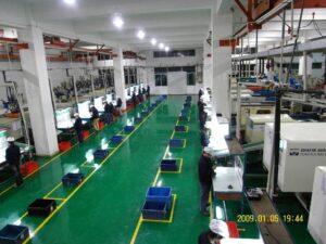
Here is the brief introduction of china high precision molds.

Draft

Draft alludes to the point of slope set between the vertical surfaces of the plastic moldings and the shape opening course. Draft is ordinarily applied to encourage discharge of the moldings from the shape. Item creators as often as possible stay away from the use of noteworthy draft, since it changes the tasteful type of the structure and lessens the embellishment’s inward volume. All things considered for products made by injection moulding china, draft is generally applied to plastic moldings to maintain a strategic distance from launch issues and incredibly complex shape plans.

Draft edges on ribs must be painstakingly indicated. In the past rib configuration, for example, a 2° draft point was applied to encourage the launch of the formed part from the shape. Regarding item usefulness, a lesser draft point might be wanted since this takes into consideration taller and thicker ribs with more prominent solidness.

Lamentably, lower draft points, (for example, % or 1°) may make the part unreasonably stick in the form. This issue of staying upon part launch can be intensified when shaping with mica-and additionally glass filled materials that have low shrinkage and high surface harshness. All things considered, the passable draft point is an unpredictable capacity of the material conduct, handling conditions, and surface completion.

A base draft point of 0.5° is regularly utilized, with 1 to 2° ordinarily applied by material provider proposals. Unpleasant and finished surfaces ordinarily require extra draft, with an extra 1° of draft regularly applied per 20 1um of surface unpleasantness or surface profundity. Table 2.3 gives some prescribed draft edges to a couple of various surface completions and materials; the suggested draft point increments with the surface harshness. Concerning the material properties, the draft point should increment for glas-filled as well as low shrinkage materials yet might be diminished for exceptionally adaptable materials, for example, delicate PVC.

Undercuts

An undercut is an element in the item structure that meddles with the launch of the embellishment from the shape. These structure highlights incorporate, for instance, a window in a side divider, a shade over the base mass of the section, a flat chief, and a snap bar or”finger.”

To give some knowledge into why these highlights are normally dodged by high precision plastic injection mould suppliers, consider three diverse however basic form structure procedures for embellishment a snap pillar with the shape shut before discharge and with the moving side withdrew and the ejectors reached out forward. Since the snap shaft is smaller at its neck than at its tip, there is an undermined in the shape that the form architect must know about and make the plan with the end goal that the part can be launched out after the shape opens. If it’s not too much trouble note that the gave plans are not planned to recommend the utilization of each of the three techniques in a solitary shape, yet just give a premise to conversation.

The plan at the left is the least complex of the three, wherein an opening or window at the base of the snap pillar permits a distension from the fixed side to center, out the territory pit underneath the undercut. This is a solid procedure, however leaves a gap in the part that changes its capacity and style.

At structure at the privilege is likewise normal, which utilizes an ejector pin with a profiled or shaped surface on its side adjoining the snap shaft. This shaped profile on the ejector pin gives a smaller than normal hole to permit the trim of the top of the pin. At the point when the form is opened and the ejectors are broadened, the pin and part will move together until the part completely clears the shape hole and can free the range from the undercut. When utilizing formed ejectors, a dowel pin or some other structure include must be utilized to keep up legitimate direction of the shaped surface as for the shape hole. Something else, the pit surfaces would not adjust and blemished parts would happen.

The plan at the middle is likewise a typical structure in which a sliding, calculated pin or”lifter” is utilized to center out the volume of the form caught underneath the undercut. After the shape is opened, the progress ahead of the lifter following up on the slanted surface of the form makes the lifter move along the side, accordingly clearing the undercut upon discharge. There are three issues related with lifters that the plastic part and form planner ought to consider while embracing their utilization. In the first place, there is the additional plan time and intricacy used to execute the structure. Second, there is the potential for wear, staying, and expanded support related with the sliding surfaces on the slider itself, on the form surfaces, and inside the ejector get together. Third, the utilization of the lifter requires sufficient leeway between highlights inside the shaped part. As showed, this specific structure likely doesn’t give adequate leeway, to such an extent that the lifter will meddle with the furthest right snap pillar if the lifter is additionally expanded.

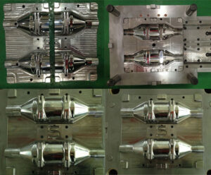
It might appear that such complexities in form configuration would direct the shirking of snap shafts, yet practically speaking, such structures are not generally hazardous for experienced shape creators. More testing than such undermining highlights is the level supervisor that is arranged inside to the part and planned with a shaped inner string. Together, these structure highlights would require a confused form plan with planned activation of different centers before discharge of the item. On the other hand, a”lost core”could be utilized in which the shape center that frames the inside highlights of the part is dissolved away after the part is formed.

Whenever the situation allows, these kinds of item configuration highlights ought to be kept away from since complex shape instruments must be structured and machined for framing and catapulting the formed part. These extra shape parts can make the form more hard to utilize and even harm the form whenever utilized inappropriately. Thus, the form configuration designer ought to distinguish risky highlights, alert the client, and work with the item configuration specialist to expel the undermines. Be that as it may, such undermines ought not be planned out of the item if the capacity gave by the feature(s) with the undercut is indispensable to the item or the expulsion of the undercut would require extra post forming tasks or the upgrade of a solitary part into various pieces.

This article is from www.injectionmouldchina.com.

Injection Molding Design

For oem/odm largest plastic injection molding companies, a point by point audit of the plastic part configuration ought to be led before the structure and production of the injection shape, The plan survey ought to consider the basics of plastic part configuration, just as different concerns related explicitly to form structure. Probably the most essential part plan contemplation are next examined.

Uniform Wall Thickness

Portions of differing divider thickness ought to be stayed away from because of reasons identified with both expense and quality. The essential issue is that good and bad divider segments will cool at various rates: thicker areas will take more time to cool than more slender segments. When launched out, leaves behind fluctuating divider thickness will show higher temperatures close to the thick segments and lower temperatures close to the slight areas.

These temperature contrasts and the related differential shrinkage can bring about huge mathematical twisting of the part given the high coefficient of warm development for plastics. Extraordinary contrasts in divider thicknesses ought to by and large be maintained a strategic distance from assuming there is any chance of this happening since interior voids might be shaped inward to the part because of over the top shrinkage in the thick areas even with broadened pressing and cooling times. (There are exemptions, obviously, for example, embed trim and gas/water help shaping that have deliberately structured thick divider areas.

The most noticeably awful part configuration, appeared at upper left, has the dissolve gated into a slight segment and afterward streaming to a thick segment with a sharp change in the thickness. This plan may prompt moldings with helpless surface completion because of nonuniform progression of the soften just as helpless surface replication and dimensional control in the thick segment identified with untimely consolidation of the plastic formed in the meager segment. The nature of the formed item would be incredibly improved as appeared at the top place. Just by gating into the thicker area, the shaped item Would have much better feel and dimensional strength since the thicker segment would permit the pressing of the more slender segment preceding its 0wn cementing. The structure would be additionally improved by progressively changing the thick segment to the meager area. All things being equal, any item plan with noteworthy varieties in divider thickness will show broadened C00ling times and diverse shrinkage rates in the good and bad areas.

A standard methodology of china fundamentals of plastic mould design is to build the ostensible thickness of the formed part in order to take out the requirement for thick segments in neighborhoods. The choice to build the divider thickness will kill numerous issues identified with part quality, yet can prompt inordinate material utilization and expanded cooling times. Hence, the best structure might be to utilize a more slender divider thickness along with vertical ribs in those zones requiring more prominent firmness and quality. The tallness as well as thickness of the ribs might be adjusted to change the relative solidness all through the part.

The injection forming process of injection molded plastic manufacturers china  is one of a kind contrasted with other embellishment process in its capacity to monetarily give complex structures. The last two section structures show elective techniques that are progressively normal. At the base left is a more slender divider area with a network of slim, short ribs. At the base right is the equivalent thicker divider area that has been dimpled 0n the two sides to diminish the compelling divider thickness. The two procedures are valuable diminishing the divider thickness while as yet expanding the measure of material away from the part’s nonpartisan pivot in twisting, along these lines adding to a noteworthy increment in firmness without an expansion in the material utilization. Besides, the two methodologies give a noteworthy increment in surface territory, which will bring about improved shape cooling and trim profitability.

This article is from www.injectionmouldchina.com

Product Design in Mould Manufacturing Process

The product development process of chinese injection molding companies commonly starts with product definition which incorporates a conventional investigation of the market, bench-marking of contenders, meaning of the product particulars, and evaluation of expected benefit. In the event that administration concurs that another product is to be grown, at that point a suitable group is collected to play out the early idea plan and business development in the injection mold manufacturers china.


During this first stage, the surmised size, properties, and cost of the product are evaluated. Portrayals, models, and models might be delivered to impart and evaluate the feasibility of the idea.


Regarding gainfulness, showcase concentrates of pom moulding products china during the early product development stage will endeavor to foresee the expected deals at different value focuses. Simultaneously, work and task quotes will build up the spending plan required to create and offer the product for sale to the public. An administration survey of the idea structure, deals figure, and spending plan is normally performed to evaluate the probability of the business achievement; of proceeded with product development. As of now, the proposed product development task might be endorsed, declined, retired, or altered as needs be.


Form configuration is one huge movement in an a lot bigger product development process. Since product and shape configuration are associated, it is helpful for both product and form configuration architects to comprehend the plastic part development process and the job of form structure and shape making. A run of the mill product improvement process is introduced, which incorporates various stages for product definition, product plan, business and creation development, increase, and dispatch.


While there are numerous product development forms for the products made by injection moulding china, most offer two basic attributes: One is an organized development plan [1] to facilitate simultaneous structure exercises to guarantee following and culmination of the plan and assembling as per timetable and execution necessities. Another is a gated administration process [2] to relieve hazard by designating bigger spending plans simply after critical surveys at venture achievements.


The product development process is part into different stages isolated by endorsement cost doors. A diagram of each stage is next given.


In the event that the venture is affirmed and a spending plan is dispensed, at that point the product development process proceeds, generally with extra assets to perform further examination and structure. During this subsequent stage, every part in the product is structured in detail. The plan of plastic segments may incorporate the thought of stylish, basic, warm, fabricating, and different prerequisites. Plan for assembling strategies might be utilized to distinguish issues that would repress the compelling assembling of the segments. Structure for get together strategies might be utilized to diminish the quantity of segments, determine resistances on basic measurements, and guarantee the monetary gathering of the completed product.


The result of the underlying product configuration stage (during that time the executives endorsement is an productized and approved product structure. The term”detailed design”implies that each part is completely determined concerning material, mathematical structure, surface completion, resistances, provider, and cost. In the event that a custom plastic segment is required, at that point cites for these formed parts are regularly mentioned during this stage. These expenses are introduced to the board alongside the point by point plan for endorsement. In the event that the product structure and expenses are satisfactory, at that point the necessary financial plan is assigned and the product improvement currently centers around assembling.

This article is from www.injectionmouldchina.com.