Shrinkage Analysis

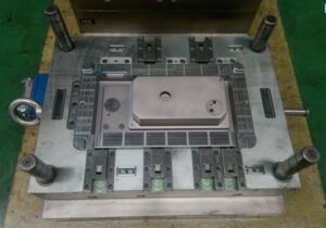
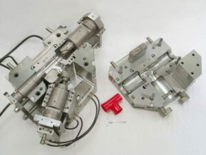
As a rule, for high precision plastic injection mould suppliers, inadmissible nonuniform shrinkage isn’t perceived until after the shape is planned, manufactured, and tried. At times, the expansion of sprinters and entryways might be a moderately basic and cheap action. In different cases, nonetheless, the expansion of two doors may end up being costly, with negative repercussions on weave line areas and feel. For instance, the alteration from a two-drop “straight bar”” complex to a four-drop “H”or”X” style complex may require the buying of another complex, the expansion of bores to the A-side of the form, and the re-directing of cooling lines. By and large, the form planner and disintegrate will initially attempt to address the shrinkage conduct through preparing or material changes as portrayed in  oem/odm automotives mold factory.

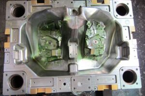
For approval of the portrayed shrinkage examination, economically accessible soften temperature and weight sensors were stacked to supplant ejector pins in a form for creation of 3.2 mm thick, ASTM pliable bars [9]. As appeared in OEM/odm medical injection moulding design factory, every infrared dissolve temperature sensor (Futaba EPSSZL) supplanted an ejector pin that heaps a soften pressure sensor (Futaba SSB1KN) situated inside the ejector retainer plate. The weight applied by the polymer liquefy to the uncovered surface of the temperature sensor gave a push power to the dissolve pressure sensor.

A Design of Experiments (DOE) was executed as appeared in Table 10.1 for trim the test examples of polypropylene. The 18-run configuration is full factorial as for 3 degrees of pack weight and 3 degrees of slam speed. The form coolant and barrel temperatures were hindered to rehash the full factorial plan at low and significant levels of temperature.

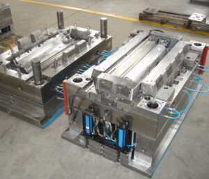
Figure 10.11 plots the obtained soften temperature signal close to the entryway for the primary pattern of every one of the DOE runs; the striking follow relates to run 14. The temperature signal starts close to the form coolant temperature. As the polymer liquefy passes the sensor, the temperature moves to a level close to the barrel temperature. The detected dissolve temperature fluctuates with the barrel temperature and infusion speed settings. There is an outstanding rot in the detected soften temperature as the warmth is directed to the cooler shape as per the investigation of Eq, 9.4. There is a later deferral in the cooling somewhere in the range of 20 and 25 s, likely because of inert warmth of combination as the polymer sets.

Figure 10.12 plots the depression pressure close to the door for similar cycles plotted in china precision plastic injection die manufacturers. The nature of the signs is incredible considering the utilization of the temperature sensor as a heap transmission medium. The impact of the three pack pressure settings is obviously noticed comparing to top depression pressures around 25, 50, and 75 MPa. A slight counterbalance in the hour of the pinnacle soften pressure is seen which compares to the adjustments in the infusion speed. The barrel and coolant temperature settings influence the pinnacle pit pressure just as pace of rot during pressing.

The particular volume of the polymer is plotted in high precision plastic injection mould manufacturers for run 14 of the DOE utilizing the weight volume temperature (PvT) shrinkage model of china industrial injection moulding manufacturers. During the embellishment cycle, the warmed polymer changes from semicrystalline strong to shapeless liquid around 170°C. During flling and pressing, expanded weight packs the dissolve thus lessens the particular volume. The particular volume at that point diminishes as the polymer in the pit encounters further pressing/cooling.

This article is from https://www.injectionmouldchina.com

Hot Runner Mold

Hot runner molds from China mould produce services factory ought to be considered at whatever point gating adaptability, cycle productivity, and material effectiveness are significant. In a hot runner system, the feed system is encased in a warmed channel with the goal that the plastic stays liquid during the trim cycle. Since the plastic doesn’t cool in a hot runner system, there is no compelling reason for oem/odm industrial mold design factory to plasticize the liquefy that would be needed to fill the feed system,

■inject the material that would fill the feed system, hang tight for the material in the feed system to cool, open the shape a generous add up to eliminate the feed system as in a three-plate form,

■de door the feed system from the shaped items, or

■re-granulate or dispose of the runner system,

For every one of these reasons, it isn’t phenomenal for hot runner molds to work with 20% quicker process durations and 20% less piece material than a traditional two-plate or three-plate cold runner shape. Nonetheless, hot runner molds do require a higher beginning venture than either two-plate or three plate molds and furthermore require hot runner regulators to keep up the soften temperature. While hot runners may appear to build vitality usage [2], the related increases in improved material use and trim profitability give net decreases to add up to vitality costs.

China industrial injection moulding manufacturers give a part through an isometric perspective on a hot runner system. This hot runner configuration incorporates a hot sprue bushing, complex, two drops or “spouts,” four warmer control zones, and different parts. During activity, the material from the embellishment machine’s spout will go down the hot sprue bushing to the essential runner situated in the complex. The dissolve at that point crosses down the length of at least one runners to downstream hot runner spouts. The length of the spout is controlled by the good ways from the centerline of the complex to the gating area of each shape depression.

Contrasted with cold runner plans, the distances across of the runners and drops in a hot runner system might be very enormous, since all the material in the hot runner will in the end be constrained into the shape pits. Since the polymer dissolve isn’t squandered, hot runner system can have enormous runner breadths to accommodate low stream opposition and amazing transmission of the infusion strain to the shape pits. Notwithstanding, excessively huge breadths can allow the material to corrupt in the hot runner and forbid quick change overs between various plastic pitches and hues.

A segment through a hot runner form gathering is appeared. This form configuration accommodates the infusion of the plastic soften into the left and right sides of the PC bezel through a normally offset hot runner system with two drops. As can be watched, an air hole encompasses most of the hot runner system to limit heat move from the warmed complex and spouts to the colder form steel.

During trim, the dissolve pressure applied on the essences of the shape depression and hot runner system will bring about powers that would will in general reason the hole embed and the hot runner system to divert. Push cushions, in some cases machined from titanium, are utilized to move these powers from the hot runner system to the top clip plate while moving a negligible measure of warmth. With hot runner molds, cooling lines or potentially protecting sheets ought to be utilized with the top brace plate to forestall the exchange of noteworthy warmth to the platens of the embellishment machine.

The hot runner system configuration gave is a moderately straightforward plan, which uses warm entryways that will be determined in the following section. In this plan, the hot runner spouts are concentric with the door removed gave in the depression embed. Since the complex will extend with changes in the complex temperature, the complex is permitted to grow and slide over the top surface of the spouts. The complex and spouts are kept up in pressure in the stature bearing to forestall any noteworthy measure of liquid polymer from getting away.

There are a wide range of hot runner system arrangements, including drops that are strung and in any case fit to the complex. Various designs of hot runner manifolds are additionally normal. The straight-bar complex is among the easiest. Two other normal plans incorporate the “H” and”X” complex plans. The”H” complex gives different branches to take care of the polymer dissolve through essential, optional, and even tertiary runners situated on the centerline of the complex as like the plan. The”X” complex uses a more straightforward plan wherein all essential runners exude legitimately from the focal point of the complex at the hot sprue bushing. This plan ordinarily accommodates more productive material usage. On the off chance that various drops are being taken care of, numerous manifolds may likewise be stacked.

Hot runner plans have expanded in multifaceted nature and capacity with designs undeniably more unpredictable that those appeared. Later presents stack molds in which at least two hot runner system are stacked in the shape stature heading to consider augmentation of the form depressions without an expansion in brace weight. Hot runner providers can likewise plan “seven-leg specials” in which the lengths and stretching of a hot runner are hand crafted to accomplish unique application prerequisites, commonly for multigated parts, for example, car body boards. The form originator ought to talk with various hot runner providers to comprehend the advantages and issues related with accessible hot runner system.

This article is from https://www.injectionmouldchina.com

Three Plate Mold

A separated isometric perspective on a completely open three plate mold configuration is given; the view gave does exclude the ejector lodging and related parts, since these are not key to the activity of the three-plate mold. Three-plate molds, the high precision molds made in china are contained three mold areas that move comparative with one another, with each segment comprising of one 0r more plates. The expansion of a subsequent splitting plane between the A plate and the top clip plate takes into consideration sprinters to be situated over the mold cavities and to cross across the width and length of the splitting plane without meddling with the mold holes. Thus, the three-plate mold gives more noteworthy opportunity regard to gating areas and the feed framework mold. An additional advantage is that three-plate mold of high precision plastic injection mould suppliers regularly give programmed partition of the molded parts from the feed system.

China industrial injection mold suppliers give a part through a completely shut three-plate mold. In this plan, the polymer soften streams down the sprue bushing over the thickness of the top clip plate and stripper (or”X”) plate. The polymer dissolve at that point streams along sprinters situated in the splitting plane (alluded to here as the”A-X”parting plane) between the A plate and the stripper plate. Tightened sprues are then used to pass on the soften through the thickness of the A plate and any cavity embed uphold plate t0 the mold holes.

Sprue pullers, likewise known as”sucker pins,” are utilized close to the sprue areas and different bits of the sprinter to guarantee that the feed framework stays with the stripper plate; the mold architect should plan the sucker pins with the end goal that they don’t limit stream. In the feed framework plan, the pins have a little breadth and profundity contrasted with the elements of the essential sprinter. To additionally diminish the stream impediment in the plan of Fig. 6.8, they could be moved further away from sprue bushing.

Mould produce factory gives a segment through a halfway opened three plate mold. Subsequent to trim, the B side of the mold is pulled away from the A side, driving the mold to open at the splitting plane between the An and B plates; the ejector framework, back brace plate, and related parts have been discarded. A spring situated between the A plate and the stripper plate might be utilized to cause early partition of the A-X separating plane. The B side keeps on opening, with the separation between the A and the B plates constrained by the length of a stripper jolt interfacing the A plate to the B plate. The free length of the stripper jolt must be adequate to consider the launch of the molded parts. A run of the mill mold opening separation between the An and B plates is equivalent to two to multiple times the tallness of the molded parts. This separation can be very enormous for molded parts with even moderately shallow centers.

When the length of the stripper jolt is crossed, the A plate will move away from the fixed platen alongside the B plate. The A plate will cross the free length of the stripper jolt for the stripper plate. The free length of this stripper jolt decides the mold opening separation between the A plate and the stripper plate.

Likewise with the A plate stripper jolt, the length of the X plate stripper jolt must be adequate to take into account the expulsion of the feed framework. When the A plate crosses past the free length of the X plate stripper jolt, the stripper plate will move away from the top brace plate alongside the A segment, B segment, and discharge arrangement of the mold.

It gives a segment through a completely opened three plate mold without the ejector system or back clasp plate. During mold activity, the mold opening speed and position must be deliberately decided and controlled to accomplish a productive and completely programmed cycle. On the off chance that the mold opening measurements are not painstakingly determined, at that point the feed framework may not be dependably shot out or the mold can be harmed. To advance the mold activity, the mold opening separations in numerous three-plate molds can be balanced by changing the situation of nuts on the stripper screws or by including washers between the plates and the finishes of the stripper fasteners.

It ought to be noticed that this three plate configuration has been made as minimized as conceivable as for mold opening separations, determination of plate thicknesses, and stripper jolt lengths. Accordingly, it is quick to analyze the plan of the three-plate mold with that of the two-plate mold. The extra plates and parts in the three-plate mold have expanded the stack stature by 44 mm (134 inches) and the mass by 30 kg, moderately little increments (on the request for 20 %). Nonetheless, the three-plate mold has a mold opening separation of 250 mm, a lot more noteworthy than the mold opening separation of 75 mm for the two-plate mold.

This bigger mold opening separation is unwanted, since it adds to the mold opening and shutting time and may likewise keep the mold from working in some infusion molding machines with restricted light.

This article is from https://www.injectionmouldchina.com/

Mold Filling Consideration

For a worthy molded part from injection mould china to be delivered, the polymer soften should totally fill the mold cavity. Appropriately, the divider thickness of the molded part and the gating areas must be indicated with the end goal that the soften can navigate from the doors to the edge of the hole. Mold filling examination by china precision plastic injection die manufacturers is utilized to guarantee that the soften can not just fill the shape at air conditioning trim weights, however fill the mold as planned to accomplish the ideal quality.

Hole filling examination might be performed for an assortment of purposes. On the most fundamental level, mold filling examination is helpful to guarantee that the shape cavity can be loaded up with the plastic liquefy given the soften pressure that can be conveyed by the embellishment machine. Normally, the dissolve compel needed to fill the hole is under 100 MPa (around 15,000 psi) despite the fact that most present day machines can gracefully twice this sum. This well being edge between the required and accessible dissolve pressures gives a remittance to the weight drop in the feed framework, and furthermore guarantees that the mold can be filled given potential changes in the material properties or trim cycle.

Pit filling investigation is additionally performed to guarantee that the filling pressures are not very low, since exceptionally low soften pressures are characteristic of a poor shaped part structure or inappropriate preparing conditions. Unnecessarily thick divider areas will bring about low weights, extreme material expenses, and broadened process resistance. In such cases, the ostensible divider thickness ought to be diminished and ribs or different highlights used to give the vital quality and solidness. Now and again, exceptionally low dissolve weights can show inappropriate occupying time, mold temperature, or liquefy temperature.

These handling conditions ought to be changed in accordance with lessen the preparing time and cost to the detriment of higher liquefy pressures. On a further developed level, pit filling investigation is valuable to foresee the dissolve front headway in the pit and recognize the area of sew lines, end of fill, and other marvels before the shape is fabricated and tried. These outcomes can be utilized to change the gating location(s), kind of door, depression thicknesses, ejection peak areas, vent areas, and other plan boundaries.

While current PC shape filling recreations can give nitty gritty outcomes to complex depression geometries,”lay-flat”cavity filling examination remains incredibly helpful. This manual investigation gives a methods by which the shape creator can comprehend the essential stream conduct and create valuable assessments to decide the mold plan and cycle conditions or approve PC recreation results. To play out this investigation, the mold configuration engineer must comprehend the basics of dissolve rheology and the administering conditions for stream. Thereafter, a strategy for pit filling examination will be introduced and approved.

The part and mold configuration of mould manufacturing factory must be grown with the end goal that the shape pit can be totally filled by the polymer dissolve at useful soften pressures. Therefore, filling investigation of the shape hole ought to be performed to check the part divider thickness for a given material and aid the entryway choice and preparing conditions.

Present day molding machines of high precision molds made in china can commonly convey injection weights of roughly 200 MPa (30,000 psi). Be that as it may, a lower dissolve weight ought to be accepted for filling the hole to take into consideration when quality control checks for injection moulding:

■a lower required brace weight,

■reasonable weight drop in the feed framework, and

■a factor of security for mistakes in suspicions.

Practically speaking, a dissolve weight of 100 MPa is ordinarily determined as a most extreme breaking point for the pit filling pressure. The greatest pit weight might be indicated higher if the trim machine of china cnc machine for mold making is known to have a high injection pressure, or if the mold’s feed framework is deliberately intended to acquire a little weight drop (by means of a hot sprinter framework for instance). If a mold is hard to fill, decays will by and large attempt to repay by expanding the mold and liquefy temperatures, broadening the sprinter widths, attempting lower-consistency plastics, lastly changing the divider thickness of the shape hole. Then again, if a mold is extremely simple to fill, decays will by and large decrease the shape and soften temperatures while expanding the injection speed to abbreviate the process duration.

This article is from https://www.injectionmouldchina.com/

Cavity Layout for the Mould

After the center and cavity embeds have been at first estimated, the mold format can be additionally evolved and the mold base chose. It is basic to arrange a mold base with properly estimated plates and materials, since any missteps in the mold base determination can devour critical time and cost. To decide the suitable size, china industrial injection mold suppliers should initially mastermind the mold cavities and give stipends to the cooling and feed frameworks. A while later, china tooling-building services manufacturers should choose a standard size from accessible providers and confirm reasonableness with the decay’s trim machine.

The objective of cavity format configuration is to deliver a mold plan that is conservative, is anything but difficult to fabricate, and gives shaping efficiency. In the event that a solitary cavity mold is being structured, at that point the hole is commonly situated in the focal point of the mold, however gating prerequisites may require setting the mold cavity askew. For multi-hole molds, there are basically three crucial cavity format: pits set along one line, holes set in a network, or pits set around a circle.

Putting all the pits along a line, is a basic however helpless structure. Except if the supplement calculations are long and limited, the subsequent mold spread out produces a mold that has a high angle proportion. As a rule, the width-to-length proportion of the jumping envelope around all holes ought to be kept under 2:1.

Higher viewpoint proportions will require the utilization of huge molds that are fundamentally underutilized while simultaneously delivering basic loadings over the mold for which embellishment machine platens may not be structured. Moreover, the utilization of such a line design can bring about an unequal feed framework with lopsided depression filling and poor molded part quality.

As an option in contrast to a direct design everything being equal, it is entirely expected to put depressions in a matrix as appeared in Fig. 4.18. This structure is generally normal for applications requiring high creation volumes when the quantity of cavities is a numerous of 2, for instance, 4, 8, 16, 32, and so forth. There are two essential advantages to a framework format. Initially, the framework design will bring about a smaller mold with a satisfactory angle proportion. Second, the framework format loans itself well to normally adjusted feed framework designs.

While the matrix format is conservative and normal, it can bring about a feed framework plan with various branches. To diminish the feed framework unpredictability and guarantee more adjusted dissolve filling, a round format is now and then utilized when the molded parts are moderately little or when the quantity of mold pits is generally low, for instance, eight or less. One such design in which all the depressions are given at an equivalent good ways from the focal point of the mold. The essential detriment is that such a roundabout format requires a bigger mold surface region than the recently examined matrix designs.

While the recently talked about formats are the most widely recognized, mold creators of injection manufacturing factory can use other design structures, including blends of the above designs. The subsequent format is a minimized and adjusted plan for six holes. Once more, the originator ought to build up the design that is best for the application’s math and necessities.

This article is from https://www.injectionmouldchina.com

Mold Cost Overview

High precision plastic injection mould manufacturers know it clearly that there are three principle cost drivers for mold items:

  1. the expense of the mold and its upkeep,
  2. the materials cost, and
  3. the preparing cost.

Beneath gives a breakdown of these essential cost drivers and their hidden parts. Note that these expenses do exclude roundabout costs of high-precision molds factory, for example, offices, managerial overhead, incidental advantages, or benefits. In any case, such aberrant expenses might be represented through the modification of hourly rates or use of backhanded cost rates.

Despite the fact that most shaped molds have a similar cost drivers, the extent of expenses differs generally by application for different china industrial injection mold suppliers. It shows the cost breakdown for a ware application, (for example, a link attach with a creation volume of 10 million pieces) and a uniquely application, (for example, a custom electrical connector with a creation volume of 100,000 pieces). While these two items are around a similar weight, it is seen that the greatness and extent of expenses are immeasurably extraordinary. The item part will in general have lower costs because of economies of scale that permit (1) amortization of the shape cost across immense creation amounts, (2) advancement of the embellishment cycle for lower forming expenses, and (3) lower material expenses related with mass acquisition of sap. As Fig. 3.3 proposes, the material expenses speak to most of the complete shaped part cost in ware applications though the form/tooling expenses can rule for custom moldings with low creation amounts.

where Cnol/part is the amortized cost of the form and upkeep per part, Cmateria/part is the material expense per part, Cprocess/part is the handling coSt per part, and yield is the division of shaped parts that are satisfactory. Every one of these terms will be therefore assessed. To exhibit the cost assessment technique, every one of these cost drivers is examined for the PC bezel. The model examination accept that 1,000,000 sections are to be shaped of ABS from a solitary pit hot sprinter form.

The expense of the shape for a given application is assessed later. Given the gauge or a statement for the form cost, Crotal shape, the expense of the form per part can be surveyed as where ntotal is the absolute creation amount of parts to be formed, and fmaintenance is a factor related with keeping up the form. Most disintegrates play out a few degrees of upkeep, including:

■preventive upkeep after each embellishment run, .

■inspections and minor fixes on an irregular premise,

■scheduled general shape support on a quarterly or semiannual premise, and

■mold revamping as important.

The requirement for shape support and fix is identified with the quantity of embellishment cycles played out, the properties of the plastic and form materials, the preparing conditions, and the nature of the shape. When in doubt, yearly support expenses can be assessed as 10% of the form buy cost, yet will change with the plan, materials, and preparing conditions in application. As the sap turns out to be more grating comparative with the hardness of the form, the wear of the shape quickens and more upkeep is required. Then again, a very much structured, solidified form should show lower support costs when utilized with an unfilled low-consistency plastic.

where Vpart is the volume of the formed part, Ppolymer is the thickness of the shaped polymer at room temperature, Rpolymer is the expense of the formed polymer per unit weight, and I scrap is the absolute extent of material expended including startup, deformities, and scrap related with the feed framework. This article is from https://www.injectionmouldchina.com