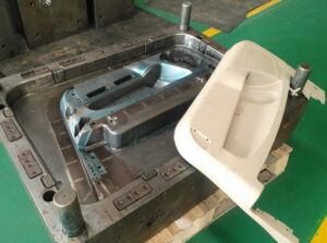
In the past model, the diversion of the side divider was not an issue. In any case, this issue would almost certainly be huge if the dissolve pressures were higher, the mold cavity was more profound, or the embellishment resistances were more tight. The mold creator from china mould produce services could increment the width of the cheek to decrease the side divider avoidance. In any case, this approach adds huge size and cost to the form. Another option is to use interlocks on the splitting plane close to the edges of the mold to move part of the bowing burden from the fixed portion of the mold to the moving portion of the mold.
Round and rectangular form interlocks are appeared in Fig. 12.20. The two sorts of interlocks ought to be put 0n the splitting plane and as near the form cavities as could be expected. When all is said in done, the rectangular interlock will give more noteworthy protection from diversion because of its bigger size and cross-sectional region across the interlock. However, round interlocks are accessible in more modest sizes and are simpler to introduce in a mold.
A detail perspective on a form configuration consolidating a round interlock is appeared in plastic precision injection mould factory. In this plan, the male interlock is found a way into a through opening in the B plate of the mold. The female interlock is found a way into a visually impaired pocket in the more profound A plate of the mold. The two interlocks firmly fit into the encompassing plates, and are held in the stature course with attachment head cap screws. It is significant that the mold deendorser doesn’t imperil the underlying respectability of the side divider by eliminating abundance mold material while joining the interlocks. At the point when the dissolve pressure is applied 0n the side divider, the interlock will move part of the heap from the A portion of the form to the B half of the mold. The utilization of the interlock adequately doubles the firmness of the side divider, bringing about a splitting of the measure of the side divider diversion.

Since bigger interlocks can convey higher burdens, the biggest interlock ought to be utilized that can be promptly consolidated into the mold plan. In the event that the interlock is presented to a sidelong power, Fateral, applied by the side divider, at that point the shear pressure in the between lock, Tinterlock, can be assessed as:
Tlnterlock= Flnteralock/Alnterlock
where Alnterlock is the cross-sectional region of the interlock at the splitting plane. In the event that the interlock is made of S7 device steel, the plan ought to give a shear pressure less than 300 MPa to stay away from disappointment. It ought to be noticed that temperature contrasts between the moving and fixed mold parts can cause misalignment of the between bolts and sped up wear during mold activity. Ordinary examination during mold support is suggested since this wear can lead straightforwardly to center movements and changes partially measurements.
Gauge the shear pressure in the 19 mm measurement interlock used to help the side mass of the cup cavity.
The essential vulnerability in this investigation is the assessment of the sidelong power applied to the interlock. This assessment of the sidelong power is confounded by the round state of the cup that gives a non-uniform cheek width between the guide pins. Be that as it may, a gauge can be given by accepting that the interlock is presented to the horizontal power from the close by surface of the mold pit. As demonstrated by the brought forth part of oem/odm industrial injection moulding design factory that represents the close by plastic, the powerful zone can be assessed as the item of the interlock width and the depression tallness.
Obviously, the interlock won’t be presented to the entirety of the horizontal power from the soften pressure applied as an afterthought mass of the mold cavity. A moderate gauge is that portion of the power will be conveyed by the interlock. This article is from www.injectionmouldchina.com
