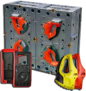
Klarm Mould Promotes Molding Design Service

Klarm Mould offers injection moulding design china and molds & tooling services china.

The mold format plan from oem/odm medical injection moulding factory is striking for two different reasons. In the first place, this plan shows 16 center supplements stuffed straightforwardly in a 4×4 lattice in one huge pocket in the center plate with no interceding mold steel. This plan is considerably more minimal and less expensive to create than a plan with 16 individual pockets for the center additions. Be that as it may, the plan will require cautious machining, completing, and gathering of the form embeds since resilience issues can cause positional mistakes and issues during embellishment, for example, coolant spills, blazing at the splitting line, or out of resistance shaped parts. Second, the plan of plastic injection mold manufacturers china is a family shape in which each set of eight holes is formed with various thicknesses and at various dissolve pressures. Planning the hot sprinter feed framework would be testing. A stacked “X” type complex like the plan of Fig. 6.13 could be utilized with various measurements for the essential sprinters to ba spear the dissolve pressures during filling.
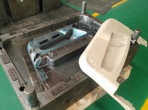
In any case, given the diverse part thicknesses and comparable pressing factors gave to every one of the depressions, the form creator ought to anticipate less shrinkage in the more slender cover moldings and indicate a lower shrinkage esteem appropriately.

The portrayed examination strategies give sensible direction to mold plan. Then again, underlying reenactments utilizing limited component investigation can be performed utilizing the definite shape math. Such underlying examination procedures [5, 6] are getting progressively coordinated with PC stream reenactments to give high-constancy expectations while likewise decreasing huge hindrances to routine execution.

The previous examination zeroed in on plate avoidance across the splitting plane. In any case, the shear stresses in the side dividers of the shape plates can likewise bring about abundance avoidance and even disappointment. This worry turns out to be particularly critical for molds with profound depressions. The cup form addresses a common situation with the heap case appeared in china large size mold. In particular, the profound pit gives a tall side divider along which the liquefy pressure, P, is applied. Assuming the pit is profound, critical shear stresses and twisting diversions can create. The width of the side divider, from the outside of the form depression to the side of the shape, is for the most part alluded to as the”cheek.”

A typical rule in form configuration is that the width of the cheek, Wcheek, ought to be equivalent to the tallness of the shape cavity, Hcavity. The most extreme shear pressure in the side divider can be assessed as a component of the stature of the shape hole, Hcavity, the width of the cheek, Wcheek, and the embellishment pressure.

Appropriately, the general guideline that the width of the cheek should rise to the thickness of the hole gives a slight factor of security under run of the mill suppositions. Despite the fact that the shear pressure may not surpass as far as possible, the form planner ought to likewise check the diversion of the side divider under load. Accepting that the side divider goes about as a just upheld pillar with a uniform burden, at that point the redirection because of twisting of the side divider can be assessed. This article is from www.injectionmouldchina.com.
Cooling Interference

The launch stage devours valuable seconds of the trim cycle, without offering a lot of benefit to the moldings. Thusly, the launch framework ought to be intended to eliminate the moldings as fast and dependably as could reasonably be expected, and afterward reset with the goal that the form might be shut and the following cycle started. To speed up the launch framework of china mould manufacturing manufacturers, some disintegrates may determine the utilization of air poppets or potentially air planes to build part discharge speeds and diminish the process duration.

To expand the unwavering quality of the discharge framework, the shape originator ought to build up the form to firmly interface with the decay’s favored part expulsion framework. While numerous molds depend on gravity drop of the moldings and the feed framework to a moving transport, disintegrates are expanding utilizing sprue pickers and gantry robots for part evacuation. When all is said in done, these frameworks don’t significantly lessen the embellishment process duration but instead give expanded control of trim’s evacuation and resulting situation while ensuring the tasteful territories. On the off chance that sprue pickers or robots will be utilized, at that point the shape architect should properly tweak the launch framework.

Ordinarily, the ejectors are utilized to peel the moldings off the center yet then hold the moldings at a controlled position. Besides, form originators ought to affirm and plan interface math in the pit and additionally feed framework that is effortlessly distinguished and exceptionally repeatable for interfacing with the part expulsion framework.

china high-precision tooling factory to Minimize Cooling Interference

There can be numerous parts in a launch framework and, shockingly, the vast majority of these segments are not effectively cooled. Thusly, the discharge framework segments can essentially meddle with the warmth move way from the embellishment to the coolant. There are two issues that usually emerge. To begin with, the launch framework segments can be made of a solidified steel that is less thermally conductive than the center supplements. In the event that the discharge framework segments are huge, at that point the form’s cooling viability will be significantly decreased. Second, the launch framework segments are gathered into the form and gave sliding fits. The outcome is that there is a warm contact obstruction over each limit between the ejection framework segments and the contiguous form. This warm contact opposition brings about lower paces of warmth move through and around segments in the discharge framework.

The impact of cooling obstruction by the discharge framework can be critical to molds & tooling services china. Consider, for instance, an ejector pin with a measurement more prominent than the ostensible divider thickness of the trim. For this situation, the ejector pin won’t move critical warmth from the connecting surface of the embellishment since

■the ejector pin has a warm contact obstruction among it and the form, and

■the ejector pin is moderately enormous.

Subsequently, the plastic in the shape pit over the ejector pin should cool by means of warmth move to the form steel around the outskirts of the ejector pin just as warmth move to the contrary side of the form, While the nearby cooling of this definite territory of the trim may not be the huge requirement on the process duration, the outcome is that this enormous ejector pin will cause a problem area in the form and less steady properties upon discharge.

Thus, the utilization of excessively enormous ejector pins by injection mold manufacturing china ought to be dodged for different, more modest ejector pins put in order to not meddle with the shape cooling. Here and there, huge launch framework segments including stripper plates, lifters, center pulls, and others are required. Such enormous segments ought to be fitted with cooling channels and effectively cooled to give predictable launch temperatures.

This article is from https://www.injectionmouldchina.com

Induction Heating

Induction heating is another way to deal with expanding the mold divider temperature before shape flling, and is seeing expanded application for micromolding, gleam, and quality. One plan is appeared in mould manufacturers china; this was created to infusion mold fortified thermoplastic composites with prevalent surface gleam and considerably no surface demoldities. T0 lessen energy utilization and warming time and high precision plastic injection mould price, just a little segment of the shape’s surface is specifically warmed by high-recurrence enlistment warming. As appeared in Fig. 9.30, a regular infusion molding machine 3 conveys polymer soften to a shape comprising of a fixed mold half 4 and a versatile shape half 5.

Preceding mold conclusion and flling, a high-recurrence oscillator 1 drives substituting current through an inductance curl (inductor) 2 briefly positioned close the surface(s) of the mold. At the point when a high-recurrence rotating current is gone through the inductor 2, an electromagnetic field is created around the inductor, which along these lines produces swirl flows inside the metal. The obstruction of the shape metal along these lines prompts interior Joule warming of the mold surface. Follows An and B in high precision mould china exhibit the expanded shape surface temperature at areas An and B brought about by induction heating; follows C and D show no underlying impact at area C and D away from the enlistment warming however later increment with the warmth move from the infused polymer soften into the mold pit.

Similarly as with all the recently portrayed methodologies for shape divider temperature control, decays wish to raise the surface temperature of the mold as fast as could reasonably be expected. The warming force through a high recurrence induction heating is relative to the square of the substituting recurrence, the square of the current, and the square of the curl thickness, among different components like china inner part mould manufacturers. In that capacity, the inductors must be painstakingly intended to locally warm the shape surface in a controlled way to keep away from an unwanted temperature circulation. For instance, an inductor was produced using copper container of 5 mm distance across and twisted as a winding with a pitch of 5 mm. The separation between the outside of the metal shape and the inductor was set to 1 cm. Analyses demonstrated that a driving recurrence of 400 kHz yielded a warming force at the mold surface on the request for 1000 W/cm2, which required roughly 10s to expand the outside of the shape by 50°C.

Contrasted with beat cooling and conduction warming, enlistment warming accommodates expanded warming rates with little included shape unpredictability. The essential issue in usage is the plan of the inductor, and specifically the dividing of its curl windings and their connection to the mold surfaces. In the event that the plan is ill-advised, at that point the warming might be restricted to low power levels. Tests showed that a warming force under 100 W/cm2 didn’t altogether build the shape surface temperature and in the long run made the over-burden breaker incite. Then again, when the force yield surpassed 10,000 W/cm2, the pace of the surface temperature increment turned out to be too steep to even consider controlling with the end goal that uniform warming was not, at this point potential; imperfections, for example, gleam abnormalities, sink marks, and so forth were seen with temperature contrasts of more than 50°C over the outside of the mold.

This article is from https://www.injectionmouldchina.com

Interlocking Core

At the point when the part math permits, slim centers with little breadths can be interlocked with the contradicting mold cavity as appeared in Fig. 9.25. Such a plan from injection moulding design china has two preferences. In the first place, the interlocking of the center with the depression offers help for the center and will in general decrease the center flexture as broke down in oem/odm industrial injection mold factory. Second, the interlocking gives a methods by which to pass on coolant from the moving side of the shape, through the center, and to the fixed side of the form. Air is ordinarily utilized as the coolant in such a plan since this coolant will be presented to the shaped part and the climate when the form is opened. While air has a low thickness, which lessens its cooling viability, plan with air channels will give considerably more warmth move than a strong center pin.

There are two regular embellishment circumstances in which there is irrelevant warmth stream from one side of the trim. The first is the long slim center indicated before in china injection mold factory, which depends exclusively on conduction down the hub of the slim pin to move heat from within the embellishment. Since the pin is so thin, there will be very lttle heat move down the length of the pin. Thus, most of the warmth must be moved to the cooling lines in the depression embed.

pom moulding parts made in china plots the warmth motion in a form having a thin center pin. The transition vectors demonstrate that there is some noteworthy warmth move around the centerline of the pin towards the coolant at its base. Nonetheless, the pin’s cross-sectional zone is little to the point that there is an overwhelming outspread warmth motion at the outside of the pin. All in all, the hot plastic liquefy that is contacting the center must exchange a large portion of its warmth entirely through the plastic to the metal and cooling lines of the depression embeds.

As to the cooling of such slim centers, the form creator ought to comprehend that the cooling time will probably be stretched out because of the restricted warmth move to the coolant. A most dire outcome imaginable can be promptly examined by expecting that there is no warmth ransfer deeply. The warmth fIux in this situation is appeared in china high precision mold manufacturer. Since all the warmth must exchange through one side of the trim, the warm conduct is basically equivalent to if two layers of the plastic dissolve were on head of one another. This twofold thickness portrayal is legitimate since the temperature circulation is symmetric over the centerline so there is no related warmth motion.

Uneven warmth stream will likewise happen when forming a plastic layer on head of another material that is ineffectively conductive, as in two-shot (multishot) shaping or overmolding, In these cycles, the primary layer or item may go about as a cover that restricts the warmth stream from the polymer liquefy just injected. As in china mold component machining, the impact of the protecting layer is to confine the warmth stream to only one side of the polymer liquefy. To ascertain the warmth move rates for such uneven warmth streams, mold manufacturing factory might be utilized by subbing double the genuine thickness of the embellishment for the thickness variable, h. The net outcome is that any trim application with an uneven warmth stream will have roughly a four-overlap increment in the cooling time over an embellishment cooled from different sides.

This article is from https://www.injectionmouldchina.com