Klarm Mould Provides Competitive Molding Service

Attachment head cap screws are the most well-known latches utilized in molds. A %”13 attachment head cap screw is appeared in Fig. 12.32. The essential explanation is that attachment head cap screws have been deliberately planned [12] to enhance the exhibition of the head, strings, and fastener as a framework. In like manner, the attachment head cap screw gives a norm and efficient technique for holding numerous parts along the screw’s hub in injection mould tooling china.

The sizes and burden conveying capacity of attachment head cap screws are identified with their size, material, and medicines. Investigation of standard attachment head screw plans demonstrates that the head tallness is equivalent to the string width, and that the head distance across is around 150% of the string breadth. While the strength of the latch changes to some degree with the coarseness of the string, the rigidity of standard DIN/ISO screws can be genuinely very much assessed by accepting an extreme pressure, ultimate, of 800 MPa duplicated by the cross-sectional zone of the external string width.
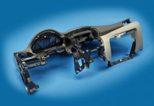
Indicate the size of the attachment head cap screws used to secure the fixed and moving parts of the PC bezel mold. Since this attachment head cap screw is utilized in a basic application of high-precision mould china where disappointment may bring about loss of gear or life, a most dire outcome imaginable is expected.

To begin with, the most extreme mass of the form is assessed accepting a strong square of steel as indicated by the measurements gave in Fig. 12.7.

Then, the most dire outcome imaginable is expected. The most dire outcome imaginable happens when the shape is braced to just one side of the trim machine without the help of the moving platen, which may happen when the form is being introduced in the embellishment machine. Besides, the most dire outcome imaginable will expect that the whole mass of the shape should be upheld by just one fixed screw, which may happen if the other cap screws are not fixed or fixed to lesser sums. The subsequent burden case is appeared in Fig. 12.33.

The applied power on the screw by the form can be assessed by adding the minutes about the finding ring.

Cap screws ought not be depended upon to find form segments given their moderately huge spiral clearances. As recently examined, an obstruction fit ought to be utilized to find one part inside the pocket of another. For equal plates or stacked parts, in any case, dowels or other finding pins ought to be utilized as demonstrated in Fig. 12.34. In this plan, concentric openings are given into the coplanar surfaces of the two plates. A dowel at that point mates with the two openings to find the two parts along the pivot of the dowel.

Assembling differences in the openings’ area, width, and roundness limit the capacity to exactly find the two parts comparative with one another. Condition 12.28 can be utilized for different sorts of fits by fluctuating the cutoff cofficients, C, for the dowel and openings as per global guidelines. Table 1 2.2 gives Coefficients to a locational-leeway fit (LC1), locational-momentary fits (LT1 and LT3), just as the loosest locational-impedance fit (LN1). Locational freedom fits are planned for parts that are commonly fixed yet can be promptly dismantled and reassembled. This fit gives similar request of resistance as strung latches, so isn’t suggested for injection molds since the huge freedom can permit sped up wear of sliding surfaces. Locational-progress fits accommodate more tight control of area, yet with the chance of impedance between the dowel and the opening which upsets the shape get together.

This article is from https://www.injectionmouldchina.com
Induction Heating

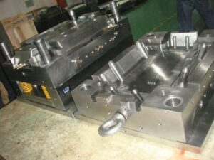
Induction heating is another way to deal with expanding the mold divider temperature before shape flling, and is seeing expanded application for micromolding, gleam, and quality. One plan is appeared in mould manufacturers china; this was created to infusion mold fortified thermoplastic composites with prevalent surface gleam and considerably no surface demoldities. T0 lessen energy utilization and warming time and high precision plastic injection mould price, just a little segment of the shape’s surface is specifically warmed by high-recurrence enlistment warming. As appeared in Fig. 9.30, a regular infusion molding machine 3 conveys polymer soften to a shape comprising of a fixed mold half 4 and a versatile shape half 5.

Preceding mold conclusion and flling, a high-recurrence oscillator 1 drives substituting current through an inductance curl (inductor) 2 briefly positioned close the surface(s) of the mold. At the point when a high-recurrence rotating current is gone through the inductor 2, an electromagnetic field is created around the inductor, which along these lines produces swirl flows inside the metal. The obstruction of the shape metal along these lines prompts interior Joule warming of the mold surface. Follows An and B in high precision mould china exhibit the expanded shape surface temperature at areas An and B brought about by induction heating; follows C and D show no underlying impact at area C and D away from the enlistment warming however later increment with the warmth move from the infused polymer soften into the mold pit.

Similarly as with all the recently portrayed methodologies for shape divider temperature control, decays wish to raise the surface temperature of the mold as fast as could reasonably be expected. The warming force through a high recurrence induction heating is relative to the square of the substituting recurrence, the square of the current, and the square of the curl thickness, among different components like china inner part mould manufacturers. In that capacity, the inductors must be painstakingly intended to locally warm the shape surface in a controlled way to keep away from an unwanted temperature circulation. For instance, an inductor was produced using copper container of 5 mm distance across and twisted as a winding with a pitch of 5 mm. The separation between the outside of the metal shape and the inductor was set to 1 cm. Analyses demonstrated that a driving recurrence of 400 kHz yielded a warming force at the mold surface on the request for 1000 W/cm2, which required roughly 10s to expand the outside of the shape by 50°C.

Contrasted with beat cooling and conduction warming, enlistment warming accommodates expanded warming rates with little included shape unpredictability. The essential issue in usage is the plan of the inductor, and specifically the dividing of its curl windings and their connection to the mold surfaces. In the event that the plan is ill-advised, at that point the warming might be restricted to low power levels. Tests showed that a warming force under 100 W/cm2 didn’t altogether build the shape surface temperature and in the long run made the over-burden breaker incite. Then again, when the force yield surpassed 10,000 W/cm2, the pace of the surface temperature increment turned out to be too steep to even consider controlling with the end goal that uniform warming was not, at this point potential; imperfections, for example, gleam abnormalities, sink marks, and so forth were seen with temperature contrasts of more than 50°C over the outside of the mold.

This article is from https://www.injectionmouldchina.com
Gate

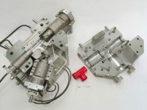
The item and mold designer of mold manufacturer factory will regularly cooperate to decide the gating location(s) in light of numerous elements including the kind of sprinter framework, stylish prerequisites, expected sew line areas, quality and direction contemplations, and dimensional control. By and large, expanding the quantity of entryways will improve shaping profitability and dimensional soundness yet with expanded form unpredictability and more noteworthy number of sew lines.

For instance, consider the screen bezel with the quantity of entryways equalto 1,2,3, or 4. For variety, accept that the plans with 1 and 3 entryways utilize cold sprinters with edge doors into the inner casing of the bezel while the plans with 2 and 4 entryways utilize hot sprinters with warm sprue doors into the back substance of the encompassing edge.

The subsequent filling designs for the different gating alternatives are portrayed. It is seen that for every one of the entryway plans, the polymer liquefy streams radially from the door and afterward changes to a direct stream design. The weave line areas are portrayed as thick lines; the quantity of sew lines increments relatively with the quantity of doors. The stream length is the good ways from the entryway to the sew line. In every one of the gating plans from china mould manufacturing manufacturers, the gating areas have been chosen so every one of the stream length are roughly equivalent.

It ought to be perceived from the depression filling that more drawn out stream lengths will require higher soften pressures. One advantage of utilizing numerous entryways is the capacity to infuse the polymer liquefy all the more rapidly into the depression while keeping up a similar polymer stream rate and shear rate in the Cavity. Appropriately, the recreation utilized a 1 S injection time for the single door plan, 0.5 s for the two entryway plan, 0.33 s for the three entryway plan, and 0.25 s for the four door plan. The subsequent liquefy pressures for every one of the gating plans are appeared in oem/odm 2 shot injection moulding factory. It is seen that every one of the soften pressure accounts are firmly adjusted all through a significant part of the hole filling measure, yet the plans with less doors must have longer occupying occasions and dispatching pressures so as to drive the polymer liquefy t0 the stream length required.

The reproduction results intently follow the outcomes. The single door configuration is likely an unsatisfactory alternative because of the high injection weights of 160 MPa. Besides, the area of the weave line so far fr0m the entryway will probably bring about an extremely feeble sew line on the grounds that the pressing phase of the trim cycle will be probably not going to make up for volumetric shrinkage of the polymer dissolve as it cools. Accordingly, the part is probably going to have exorbitant nonuniform shrinkage, warpage, and an exceptionally frail weave line. Any of the other gating plans will bring about much lower soften pressures and improved part quality.

The determination of the number and area of entryways is basic as for the mold plan and trim efficiency, thus ought to be made with the endorsement of the item fashioner. It is frequently conceivable to improve the item quality with expanded interest in innovation or material expense. As for the bezel, for instance, the presence of the weave lines could be improved through the enlistment warming of the mold surface. On the other hand, all knitlines could be disposed of by eliminating the inward window in the bezel where the screen would dwell. This region could then be focus gated with a solitary sprue, and afterward the inside window reproduced by machining around the edge of the interior edge. While it would acquire extreme work and material costs, such a mold plan technique is technically straightforward.

This article is from https://www.injectionmouldchina.com.

Cavity Filling Prediction

The material cost, handling cost, and natural effect of molded parts are totally diminished with decreases in divider thickness. In any case of injection mold manufacturing china, limiting the divider thickness can make the mold cavity hard to fill and antagonistically increment clip weight. To gauge the compel needed to fill a mold, the form architect must know the complete separation that the stream is needed to head out to fill the mold. Hence, the mold creator should choose the gating location(s) to adjust the stream between the various parts of the form. Since this is a one-dimensional stream investigation, highlights, for example, ribs and managers are ignored. These highlights are probably going to fill on the off chance that they are moderately little contrasted with the essential stream way.

Forecast of the weight drop over the form cavity, OP, can be made given the stream length and the straight stream speed of the dissolve by use of either Eq. 5.17 or 5.22. The essential suspicion in the assessment of filling pressures is that the dissolve speed will be kept up at a consistent incentive as the liquefy proliferates from the entryway to the furthest limit of the form. In principle, such a uniform soften speed could be accomplished via cautious smash speed profiling. Practically speaking, complex form calculations block the acknowledgment of uniform soften speeds, and smash speed profiling is only from time to time utilized towards this reason in any case. Accordingly, the liquefy speed will fluctuate generously from the door (where the speed is at first extremely high because of the little cross-sectional zone of the soften) to the point of end of fill. All things considered about china large size mold, the assessment of filling pressures is imperative to guaranteeing that the moldings can be made with the mold structure and the plastic materials utilized.

To anticipate the filling pressure in complex items physically by lay-level examination, it is important for china mould manufacturing manufacturers to deconstruct the calculation into a progression of basic sections. The stream in each section would then be able to be independently examined utilizing the Newtonian or force law models relating compel drop to stream rates in the fragment. Returning now to the PC bezel appeared in Fig. 5.1, it might be accepted that the streams on the left-hand and right-hand sides are symmetric. In like manner, the investigation will think about only 50% of the calculation. To do the examination, any turns in the bezel will initially be fixed. While this progression isn’t fundamental for the investigation, it stresses that the examination considers just the weight drop along the length course of the liquefy stream. Next, the edges are collapsed out to uncover extra stream that is needed to fill the vertical sides of the form cavity.

The door area has been chosen close to the middle area. The lay-ilat calculation for the PC bezel is then part into two stream fragments speaking to the stream to the upper and lower bits of the form. It ought to be noted

that it is conceivable to remember changes for the channel width, for example, smaller segments because of windows, as appeared in the center lay level on the correct side of Fig.5.12.

Areas of shifting thickness ought to likewise be broken out into various stream fragments. By investigating the stream in every one of these sections, it is conceivable to give excellent appraisals of the dissolve front areas and soften pressures as the liquefy fills the mold. Then again, areas of comparable width might be lumped together to rearrange the calculation of the stream rate and filling pressures as appeared in the right-most lay level.

The item creator and form fashioner may wish to consider the compel needed to fill for an assortment of divider thicknesses, stream rates, and liquefy temperatures. Figure 5.13 gives the assessed filling compel needed to fill the depression for a scope of divider thicknesses at the material’s mid-go liquefy temperature. The base divider thickness passable for a given infusion weight can be inferred as shown in Fig. 5.13. In particular, a line demonstrating the most extreme reasonable weight is put on the diagram with the base divider thickness happening at the crossing point of the weight bend, The examination in this example shows that the base divider thickness is 1.4 mm at a soften temperature of 240°C.

There are two significant ideas that ought to be perceived while limiting the divider thickness. To start with, the base divider thickness is an element of the dissolve temperature. It is suggested that mold fashioners utilize the mid-range temperature for investigation, since this saves the open door for the disintegrate to expand dissolve temperature and consequently decrease the filling pressures if necessary. Second, the base divider thickness is likewise a component of the feed framework plan, since the weight deliverable to the cavity from the machine is subject to the weight drop through the feed framework.

This article is from https://www.injectionmouldchina.com.