Klarm Mould Provides Competitive Molding Service

Attachment head cap screws are the most well-known latches utilized in molds. A %”13 attachment head cap screw is appeared in Fig. 12.32. The essential explanation is that attachment head cap screws have been deliberately planned [12] to enhance the exhibition of the head, strings, and fastener as a framework. In like manner, the attachment head cap screw gives a norm and efficient technique for holding numerous parts along the screw’s hub in injection mould tooling china.

The sizes and burden conveying capacity of attachment head cap screws are identified with their size, material, and medicines. Investigation of standard attachment head screw plans demonstrates that the head tallness is equivalent to the string width, and that the head distance across is around 150% of the string breadth. While the strength of the latch changes to some degree with the coarseness of the string, the rigidity of standard DIN/ISO screws can be genuinely very much assessed by accepting an extreme pressure, ultimate, of 800 MPa duplicated by the cross-sectional zone of the external string width.
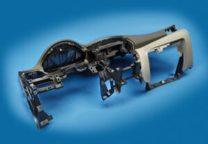
Indicate the size of the attachment head cap screws used to secure the fixed and moving parts of the PC bezel mold. Since this attachment head cap screw is utilized in a basic application of high-precision mould china where disappointment may bring about loss of gear or life, a most dire outcome imaginable is expected.

To begin with, the most extreme mass of the form is assessed accepting a strong square of steel as indicated by the measurements gave in Fig. 12.7.

Then, the most dire outcome imaginable is expected. The most dire outcome imaginable happens when the shape is braced to just one side of the trim machine without the help of the moving platen, which may happen when the form is being introduced in the embellishment machine. Besides, the most dire outcome imaginable will expect that the whole mass of the shape should be upheld by just one fixed screw, which may happen if the other cap screws are not fixed or fixed to lesser sums. The subsequent burden case is appeared in Fig. 12.33.

The applied power on the screw by the form can be assessed by adding the minutes about the finding ring.

Cap screws ought not be depended upon to find form segments given their moderately huge spiral clearances. As recently examined, an obstruction fit ought to be utilized to find one part inside the pocket of another. For equal plates or stacked parts, in any case, dowels or other finding pins ought to be utilized as demonstrated in Fig. 12.34. In this plan, concentric openings are given into the coplanar surfaces of the two plates. A dowel at that point mates with the two openings to find the two parts along the pivot of the dowel.

Assembling differences in the openings’ area, width, and roundness limit the capacity to exactly find the two parts comparative with one another. Condition 12.28 can be utilized for different sorts of fits by fluctuating the cutoff cofficients, C, for the dowel and openings as per global guidelines. Table 1 2.2 gives Coefficients to a locational-leeway fit (LC1), locational-momentary fits (LT1 and LT3), just as the loosest locational-impedance fit (LN1). Locational freedom fits are planned for parts that are commonly fixed yet can be promptly dismantled and reassembled. This fit gives similar request of resistance as strung latches, so isn’t suggested for injection molds since the huge freedom can permit sped up wear of sliding surfaces. Locational-progress fits accommodate more tight control of area, yet with the chance of impedance between the dowel and the opening which upsets the shape get together.

This article is from https://www.injectionmouldchina.com
Ejector Blade

The outcome from this model of oem/odm medical injection mold factory demonstrated that the base distance across needed to try not to clasp is on a similar significant degree as the base measurement needed to dodge unnecessary compressive pressure in the pin or over the top shear pressure in the embellishment as determined in past models. The outcomes from the above clasping examination and model are unequivocally reliant upon the length of the ejector pin; on the off chance that the pin length was longer, at that point the clasping imperative would be predominant.

The form planner ought to perform investigation for their trim application to affirm the driving limitation and guarantee a sufficient ejector plan.

By and by, there will be a variety in the powers applied to each stick. The reasons for the variety may come from contrasts in the ejector pin lengths, surface completion of the hole close to the pins, and so forth For a vigorous plan [10], it is proposed that a width half more prominent than the base needed for clasping be embraced. More modest ejector pin distances across may be wanted in some embellishment applications for stylish or pin situating necessities. In the event that the base pin breadth needed to try not to clasp is more prominent than the ideal pin measurement, at that point a ventured pin with a bigger distance across shoulder can be explored. Ventured sticks commonly have a shoulder around 1 mm bigger in breadth than the top of the ejector pin, and a normal medium length of 50 mm. At the point when essential, the form architect would custom be able to arrange ejector pins with numerous means and tightens for a given application. In the event that a ventured ejector pin is utilized by plastic mould manufacturers factory, nonetheless, the form originator ought to guarantee that a reasonable opening and freedom is determined in the help plate and center addition.

Ejector sharp edges are normally bigger breadth ejector sticks that are molded to introduce a rectangular cross-segment to the center addition. As appeared in china precision mould manufactory, the ejector sharp edge’s enormous width and little thickness take into consideration the edge to be situated straightforwardly underneath ribs. This position is exceptionally viable since the sharp edge applies the launch power at the area where the grinding powers between the embellishment and the form center are produced. Moreover, the rib is firm thus will viably launch close by bits of the rib and part. At last, the rib is definitely not a stylish surface thus ought not be antagonistically influenced by the observer mark left by the ejector cutting edge, however this is a possible territory of stress focus during the embellishment’s end-use.

The enumerating of the ejector edge, appeared in oem/odm largest plastic injection molding companies, is fundamentally the same as that recently examined for ejector pins. Clearances should be offered in the help and center additions to consider free activation of the ejector cutting edge, with the mating being given between the rectangular segment of the ejector sharp edge and the firmly mating surfaces in the center supplement. To give the rectangular opening in the center supplement, wire or plunge EDM is essential. The measure of EDM can be limited by determining the freedom opening near the outside of the shape pit, with a commonplace land length equivalent to double the width of the ejector sharp edge. The form fashioner ought to likewise guarantee that the length of movement between the ejector edge’s tightened shoulder and the limited opening in the shape embed surpass the greatest stroke of the ejector framework. Something else, the disintegrate may incidentally seize and harm the ejector edges. Given that this itemizing isn’t paltry, some shape segment providers not sell guides for ejector edges to such an extent that the center supplement is penetrated with an opening and afterward fitted with the guide from back to give the bearing surface to the ejector edge.

This article is from https://www.injectionmouldchina.com