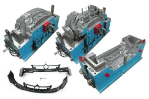
The outcome from this model of oem/odm medical injection mold factory demonstrated that the base distance across needed to try not to clasp is on a similar significant degree as the base measurement needed to dodge unnecessary compressive pressure in the pin or over the top shear pressure in the embellishment as determined in past models. The outcomes from the above clasping examination and model are unequivocally reliant upon the length of the ejector pin; on the off chance that the pin length was longer, at that point the clasping imperative would be predominant.
The form planner ought to perform investigation for their trim application to affirm the driving limitation and guarantee a sufficient ejector plan.

By and by, there will be a variety in the powers applied to each stick. The reasons for the variety may come from contrasts in the ejector pin lengths, surface completion of the hole close to the pins, and so forth For a vigorous plan [10], it is proposed that a width half more prominent than the base needed for clasping be embraced. More modest ejector pin distances across may be wanted in some embellishment applications for stylish or pin situating necessities. In the event that the base pin breadth needed to try not to clasp is more prominent than the ideal pin measurement, at that point a ventured pin with a bigger distance across shoulder can be explored. Ventured sticks commonly have a shoulder around 1 mm bigger in breadth than the top of the ejector pin, and a normal medium length of 50 mm. At the point when essential, the form architect would custom be able to arrange ejector pins with numerous means and tightens for a given application. In the event that a ventured ejector pin is utilized by plastic mould manufacturers factory, nonetheless, the form originator ought to guarantee that a reasonable opening and freedom is determined in the help plate and center addition.
Ejector sharp edges are normally bigger breadth ejector sticks that are molded to introduce a rectangular cross-segment to the center addition. As appeared in china precision mould manufactory, the ejector sharp edge’s enormous width and little thickness take into consideration the edge to be situated straightforwardly underneath ribs. This position is exceptionally viable since the sharp edge applies the launch power at the area where the grinding powers between the embellishment and the form center are produced. Moreover, the rib is firm thus will viably launch close by bits of the rib and part. At last, the rib is definitely not a stylish surface thus ought not be antagonistically influenced by the observer mark left by the ejector cutting edge, however this is a possible territory of stress focus during the embellishment’s end-use.
The enumerating of the ejector edge, appeared in oem/odm largest plastic injection molding companies, is fundamentally the same as that recently examined for ejector pins. Clearances should be offered in the help and center additions to consider free activation of the ejector cutting edge, with the mating being given between the rectangular segment of the ejector sharp edge and the firmly mating surfaces in the center supplement. To give the rectangular opening in the center supplement, wire or plunge EDM is essential. The measure of EDM can be limited by determining the freedom opening near the outside of the shape pit, with a commonplace land length equivalent to double the width of the ejector sharp edge. The form fashioner ought to likewise guarantee that the length of movement between the ejector edge’s tightened shoulder and the limited opening in the shape embed surpass the greatest stroke of the ejector framework. Something else, the disintegrate may incidentally seize and harm the ejector edges. Given that this itemizing isn’t paltry, some shape segment providers not sell guides for ejector edges to such an extent that the center supplement is penetrated with an opening and afterward fitted with the guide from back to give the bearing surface to the ejector edge.
This article is from https://www.injectionmouldchina.com
