Ejector Plate

During the launch cycle, the ejector plate is pushed ahead, making the ejector sleeve slide along the center pin and push the supervisor off the center pin. Much the same as the ejector pins and sharp edges, the withdrawal of the ejector retainer plate makes the ejector sleeve withdraw into the center supplement for the following trim cycle.

The plan of a shape with a stripper plate is appeared in oem/odm automotives mold factory. In this plan, the stripper plate replaces the B plate and is made to skim between the A plate and the help plate. To find the center embeds, a finding dowel has been set to mate the focal point of the center additions with the help plate. Attachment head cap screws (not appeared) are utilized by high precision mould manufactory to safely affix the center additions to the help plate. Segments of the stripper plate are intended to reach out underneath the base surface of the embellishment, yet not to meddle with the external surfaces of the center additions.

As appeared in oem/odm medical injection molding factory, the moldings are shot out by the kickoff of the shape when the stripper jolt connects with the stripper plate and pulls the moldings off the centers. Since the stripper plate completely draws in the lower part of the part, the launch powers are consistently circulated across the moldings bringing about low forced pressure, little disfigurement, and dependable discharge. One intriguing part of this stripper plate configuration is that the ejector retainer plate, ejector plate, and pioneer pins fill no need and can be wiped out from the shape, with the end goal that the help plate might be utilized as the back cinch plate. More regular plans of injection mold company china, nonetheless, utilize the forward activation of the ejector plate to connect with the stripper plate to discharge the formed parts.

There are some significant things to note concerning configuration subtleties An and B, which are distinguished in high precision plastic injection mould suppliers. One critical issue regarding this particular embellishment application is the area of the splitting line along the highest point of the cup. From the perspective of shape plan, the focal point of the adjusted top would be the best area to mate the stripper plate with the center addition since it would give a solid sliding surface. In any case, this mating area would bring about an unwanted and perhaps sharp observer line. In that capacity, the mating area has been moved towards the inside of the center supplement. While this gives an improved observer line area and a critical push region for the stripper plate to push on the shaped cup, it likewise brings about a sharp edge at the splitting line of the stripper plate. This sharp edge can harm the vertical surface of the center supplement, and will probably rapidly wear. Hence, the form planner may wish to keep away from the utilization of a stripper plate or solicitation the update of this part of the cup to give a level push zone to mate with the stripper plate. This article is from https://www.injectionmouldchina.com

Ejector Blade

The outcome from this model of oem/odm medical injection mold factory demonstrated that the base distance across needed to try not to clasp is on a similar significant degree as the base measurement needed to dodge unnecessary compressive pressure in the pin or over the top shear pressure in the embellishment as determined in past models. The outcomes from the above clasping examination and model are unequivocally reliant upon the length of the ejector pin; on the off chance that the pin length was longer, at that point the clasping imperative would be predominant.

The form planner ought to perform investigation for their trim application to affirm the driving limitation and guarantee a sufficient ejector plan.

By and by, there will be a variety in the powers applied to each stick. The reasons for the variety may come from contrasts in the ejector pin lengths, surface completion of the hole close to the pins, and so forth For a vigorous plan [10], it is proposed that a width half more prominent than the base needed for clasping be embraced. More modest ejector pin distances across may be wanted in some embellishment applications for stylish or pin situating necessities. In the event that the base pin breadth needed to try not to clasp is more prominent than the ideal pin measurement, at that point a ventured pin with a bigger distance across shoulder can be explored. Ventured sticks commonly have a shoulder around 1 mm bigger in breadth than the top of the ejector pin, and a normal medium length of 50 mm. At the point when essential, the form architect would custom be able to arrange ejector pins with numerous means and tightens for a given application. In the event that a ventured ejector pin is utilized by plastic mould manufacturers factory, nonetheless, the form originator ought to guarantee that a reasonable opening and freedom is determined in the help plate and center addition.

Ejector sharp edges are normally bigger breadth ejector sticks that are molded to introduce a rectangular cross-segment to the center addition. As appeared in china precision mould manufactory, the ejector sharp edge’s enormous width and little thickness take into consideration the edge to be situated straightforwardly underneath ribs. This position is exceptionally viable since the sharp edge applies the launch power at the area where the grinding powers between the embellishment and the form center are produced. Moreover, the rib is firm thus will viably launch close by bits of the rib and part. At last, the rib is definitely not a stylish surface thus ought not be antagonistically influenced by the observer mark left by the ejector cutting edge, however this is a possible territory of stress focus during the embellishment’s end-use.

The enumerating of the ejector edge, appeared in oem/odm largest plastic injection molding companies, is fundamentally the same as that recently examined for ejector pins. Clearances should be offered in the help and center additions to consider free activation of the ejector cutting edge, with the mating being given between the rectangular segment of the ejector sharp edge and the firmly mating surfaces in the center supplement. To give the rectangular opening in the center supplement, wire or plunge EDM is essential. The measure of EDM can be limited by determining the freedom opening near the outside of the shape pit, with a commonplace land length equivalent to double the width of the ejector sharp edge. The form fashioner ought to likewise guarantee that the length of movement between the ejector edge’s tightened shoulder and the limited opening in the shape embed surpass the greatest stroke of the ejector framework. Something else, the disintegrate may incidentally seize and harm the ejector edges. Given that this itemizing isn’t paltry, some shape segment providers not sell guides for ejector edges to such an extent that the center supplement is penetrated with an opening and afterward fitted with the guide from back to give the bearing surface to the ejector edge.

This article is from https://www.injectionmouldchina.com

Warpage Sources

The above segments with respect to shrinkage relates to in-plane dimensional changes in the plastic moldings. At the point when moldings misshape or twist out of plane, at that point warpage is happening. In certain applications, the dimensional changes due to warpage can far surpass the shrinkage. Moreover, warpage can be as or more hard to foresee and address. While a thorough examination is outside the extent of this book, some useful direction is

While all warpage is because of differential shrinkage, the wellsprings of the differential shrinkage fluctuate. The most straightforward reason for differential shrinkage might be a temperature inclination through the divider thickness of the trim. This marvel is appeared in oem/odm automotives mold factory. In this shape plan, the cooling framework configuration is giving nonuniform cooling. The temperature of the formed part will be higher close to the center supplement than the cavity embed. The past cooling investigation of precision plastic injection mould factory, for instance, has indicated that a temperature contrast of 5°C between surfaces of the center and the pit embeds isn’t unprecedented.

Any temperature distinction through the thickness of the moldings makes an interpretation of legitimately to various shrinkage rates through the thickness too. The contrast between the shrinkage rate on the center surface and the shrinkage rate on the hole surface will cause a subsequent strain in the part as it cools. For the case of Fig. 10.18, the center surface is higher temperature thus this side of the plastic embellishment will encounter more noteworthy shrinkage after demolding. From statics, the range of ebb and flow, Rw warpage of the trim brought about by warpage can be determined by the condition: Rwarpage=2.h/(S center S pit )

where h is the divider thickness of the trim, and Score and S depression are the shrinkage paces of the embellishment adjoining the center and hole embeds as indicated by high precision plastic injection mould suppliers. Given the range of ebb and flow, the most extreme out of plane redirection at the edges of the trim, δ, can be assessed as around: δ= W.sin(W/Rwarpage ), where W is the good ways from the middle to the edge of the embellishment.

Temperature slopes through the divider thickness of the trim are one regular reason for warpage. Another critical reason for warpage is differential shrinkage because of temperature as well as weight inclinations over the region of the part. One ordinary model is appeared in high precision plastic making mould china. In this model, the liquefy pressure in the cavity can be a lot higher close to the entryway than at the limits of the form hole.

All things considered, the volumetric and straight shrinkage in the middle will be not exactly the shrinkage around the outside of the trim. In the event that the distinction in the shrinkage is sufficiently huge, at that point the focal point of the part will twist out of the plane delivering a “pipe shape.”

The differential shrinkage appeared in high precision molds made in china is like the differential shrinkage for the PC bezel appeared in quality control checks for injection moulding. Notwithstanding, Fig. 10.15 will in general twist because of differential shrinkage while the bezel appeared in quality control checks for injection moulding won’t. The explanation is that the window in the PC bezel precisely decouples the different sides from one another, with the end goal that each side is allowed to recoil freely. Warpage would likely possibly happen because of differential shrinkage over the part if the shrinkage rate on the left side was totally different from the shrinkage rate on the correct side, and correspondingly for differential shrinkage on the top side contrasted with the base side.

This article is from https://www.injectionmouldchina.com

Shrinkage Analysis

As a rule, for high precision plastic injection mould suppliers, inadmissible nonuniform shrinkage isn’t perceived until after the shape is planned, manufactured, and tried. At times, the expansion of sprinters and entryways might be a moderately basic and cheap action. In different cases, nonetheless, the expansion of two doors may end up being costly, with negative repercussions on weave line areas and feel. For instance, the alteration from a two-drop “straight bar”” complex to a four-drop “H”or”X” style complex may require the buying of another complex, the expansion of bores to the A-side of the form, and the re-directing of cooling lines. By and large, the form planner and disintegrate will initially attempt to address the shrinkage conduct through preparing or material changes as portrayed in  oem/odm automotives mold factory.

For approval of the portrayed shrinkage examination, economically accessible soften temperature and weight sensors were stacked to supplant ejector pins in a form for creation of 3.2 mm thick, ASTM pliable bars [9]. As appeared in OEM/odm medical injection moulding design factory, every infrared dissolve temperature sensor (Futaba EPSSZL) supplanted an ejector pin that heaps a soften pressure sensor (Futaba SSB1KN) situated inside the ejector retainer plate. The weight applied by the polymer liquefy to the uncovered surface of the temperature sensor gave a push power to the dissolve pressure sensor.

A Design of Experiments (DOE) was executed as appeared in Table 10.1 for trim the test examples of polypropylene. The 18-run configuration is full factorial as for 3 degrees of pack weight and 3 degrees of slam speed. The form coolant and barrel temperatures were hindered to rehash the full factorial plan at low and significant levels of temperature.

Figure 10.11 plots the obtained soften temperature signal close to the entryway for the primary pattern of every one of the DOE runs; the striking follow relates to run 14. The temperature signal starts close to the form coolant temperature. As the polymer liquefy passes the sensor, the temperature moves to a level close to the barrel temperature. The detected dissolve temperature fluctuates with the barrel temperature and infusion speed settings. There is an outstanding rot in the detected soften temperature as the warmth is directed to the cooler shape as per the investigation of Eq, 9.4. There is a later deferral in the cooling somewhere in the range of 20 and 25 s, likely because of inert warmth of combination as the polymer sets.

Figure 10.12 plots the depression pressure close to the door for similar cycles plotted in china precision plastic injection die manufacturers. The nature of the signs is incredible considering the utilization of the temperature sensor as a heap transmission medium. The impact of the three pack pressure settings is obviously noticed comparing to top depression pressures around 25, 50, and 75 MPa. A slight counterbalance in the hour of the pinnacle soften pressure is seen which compares to the adjustments in the infusion speed. The barrel and coolant temperature settings influence the pinnacle pit pressure just as pace of rot during pressing.

The particular volume of the polymer is plotted in high precision plastic injection mould manufacturers for run 14 of the DOE utilizing the weight volume temperature (PvT) shrinkage model of china industrial injection moulding manufacturers. During the embellishment cycle, the warmed polymer changes from semicrystalline strong to shapeless liquid around 170°C. During flling and pressing, expanded weight packs the dissolve thus lessens the particular volume. The particular volume at that point diminishes as the polymer in the pit encounters further pressing/cooling.

This article is from https://www.injectionmouldchina.com

Hot Runner Section

This mold plan methodology of china precision mould manufactory diminishes the measure of machining as well as decreases the plan time and potential for machining or misalignment botches related with coordinating the two sides of a full round runner.

The essential downside related with these non-circular runners from injection mold maker china is that they offer ascent to nonuniform shear rates and shear worries over their cr0SS-segment. For instance, the trapezoidal runner is anything but difficult to machine, however the areas close to the four corners lead almost no stream down the length of the runner, The exhibition of the trapezoidal runner can be improved by adjusting the base surface to kill two of the corners. Notwithstanding, everything these non-circular sorts of runners will require to be marginally bigger and devour extra material to give a similar weight drop as a full round runner.

The recently depicted investigation can be adjusted for use with non-circular runner areas. While the outcomes won’t be as exact concerning a full-round runner, the water driven measurement, Dn, for every runner type can be determined where A section is the cross-sectional territory of the runner and Psection is the border of the crosS-segment of the runner. F0r reference, Table 6.3 gives conditions relating the predefined measurements to the water driven breadth. It ought to be noticed that the conditions in Table 6.3 have been determined accepting a 5 degree tighten point to help with the launch of the runner from the shape. This suspicion takes into account a decrease in the quantity of plan factors.

There is one other runner area that is very basic in hot runner frameworks: the annulus. In particular, numerous hot runner frameworks join valve pins down the length of the spouts to truly close off the entryway as along these lines talked about . In this plan, the polymer liquefy streams between a tube shaped drop and the round and hollow valve pin, framing an annulus.

The polymer liquefy move through an annular area might be firmly approximated by adjusting the condition for gooey stream in a strip. In particular, the width of the strip can be supplanted by the boundary of the mean breadth of the liquefy annulus, while the thickness of the strip is supplanted by the separation between the valve pin and the spout bore. Making these substitutions in Eq. 5.17 outcomes in the accompanying connection between pressure drop and stream rate in an annular segment for a Newtonian liquid. Where Dpin is the breadth of the valve pin and Dbore is the measurement of the drag through the spout. The force law model for an annulus can be correspondingly determined.

One model from high precision molds made in china is to figure the weight drop through a valve-gated spout having a length of 150 mm, a drag width of 10 mm, and a valve pin distance across of 5 mm. Expect a material with a thickness of 100 Pa-s streaming at a pace of 50 cc/s. Subbing these qualities into Eq. 6. 14, the assessed pressure drop. Another model: The essential runner in the three plate shape of Fig. 6.7 has a trapezoidal area. Compute the weight drop through a 120 mm length of essential runner with a width of 6 mm, a profundity of 8 mm, and a 5 degree tighten point. Expect the utilization of ABS with a stream pace of 44 cc/s.

This article is from https://www.injectionmouldchina.com

Mold Filling Consideration

For a worthy molded part from injection mould china to be delivered, the polymer soften should totally fill the mold cavity. Appropriately, the divider thickness of the molded part and the gating areas must be indicated with the end goal that the soften can navigate from the doors to the edge of the hole. Mold filling examination by china precision plastic injection die manufacturers is utilized to guarantee that the soften can not just fill the shape at air conditioning trim weights, however fill the mold as planned to accomplish the ideal quality.

Hole filling examination might be performed for an assortment of purposes. On the most fundamental level, mold filling examination is helpful to guarantee that the shape cavity can be loaded up with the plastic liquefy given the soften pressure that can be conveyed by the embellishment machine. Normally, the dissolve compel needed to fill the hole is under 100 MPa (around 15,000 psi) despite the fact that most present day machines can gracefully twice this sum. This well being edge between the required and accessible dissolve pressures gives a remittance to the weight drop in the feed framework, and furthermore guarantees that the mold can be filled given potential changes in the material properties or trim cycle.

Pit filling investigation is additionally performed to guarantee that the filling pressures are not very low, since exceptionally low soften pressures are characteristic of a poor shaped part structure or inappropriate preparing conditions. Unnecessarily thick divider areas will bring about low weights, extreme material expenses, and broadened process resistance. In such cases, the ostensible divider thickness ought to be diminished and ribs or different highlights used to give the vital quality and solidness. Now and again, exceptionally low dissolve weights can show inappropriate occupying time, mold temperature, or liquefy temperature.

These handling conditions ought to be changed in accordance with lessen the preparing time and cost to the detriment of higher liquefy pressures. On a further developed level, pit filling investigation is valuable to foresee the dissolve front headway in the pit and recognize the area of sew lines, end of fill, and other marvels before the shape is fabricated and tried. These outcomes can be utilized to change the gating location(s), kind of door, depression thicknesses, ejection peak areas, vent areas, and other plan boundaries.

While current PC shape filling recreations can give nitty gritty outcomes to complex depression geometries,”lay-flat”cavity filling examination remains incredibly helpful. This manual investigation gives a methods by which the shape creator can comprehend the essential stream conduct and create valuable assessments to decide the mold plan and cycle conditions or approve PC recreation results. To play out this investigation, the mold configuration engineer must comprehend the basics of dissolve rheology and the administering conditions for stream. Thereafter, a strategy for pit filling examination will be introduced and approved.

The part and mold configuration of mould manufacturing factory must be grown with the end goal that the shape pit can be totally filled by the polymer dissolve at useful soften pressures. Therefore, filling investigation of the shape hole ought to be performed to check the part divider thickness for a given material and aid the entryway choice and preparing conditions.

Present day molding machines of high precision molds made in china can commonly convey injection weights of roughly 200 MPa (30,000 psi). Be that as it may, a lower dissolve weight ought to be accepted for filling the hole to take into consideration when quality control checks for injection moulding:

■a lower required brace weight,

■reasonable weight drop in the feed framework, and

■a factor of security for mistakes in suspicions.

Practically speaking, a dissolve weight of 100 MPa is ordinarily determined as a most extreme breaking point for the pit filling pressure. The greatest pit weight might be indicated higher if the trim machine of china cnc machine for mold making is known to have a high injection pressure, or if the mold’s feed framework is deliberately intended to acquire a little weight drop (by means of a hot sprinter framework for instance). If a mold is hard to fill, decays will by and large attempt to repay by expanding the mold and liquefy temperatures, broadening the sprinter widths, attempting lower-consistency plastics, lastly changing the divider thickness of the shape hole. Then again, if a mold is extremely simple to fill, decays will by and large decrease the shape and soften temperatures while expanding the injection speed to abbreviate the process duration.

This article is from https://www.injectionmouldchina.com/

Mold Opening Rules

During the form format stage, the mold creator /injection molding service china affirms the kind of form and decides the measurements and materials for the depression embeds, center embeds, and form base. Form bases are just accessible in discrete sizes, so emphasis between the additions’ estimating and mold base choice is typical. The objective of the mold format configuration stage is to build up the physical components of the additions and mold to start obtainment of these materials. Mold material choice is additionally a significant choice, since the material properties to a great extent decide the form setting aside a few minutes and cost just as the form’s basic and warm presentation.

The mold format configuration accept that the quantity of mold holes and sort of mold has been resolved. For high precision plastic injection mould suppliers to build up the mold format, the mold opening course and the area of the splitting plane are first decided. At that point, the length, width, and tallness of the center and hole embeds are picked. Subsequently, a mold base is chosen and the additions are put in as basic and smaller a design as could be expected under the circumstances. It is imperative to build up a decent mold format plan since later investigation and itemized configuration accept the format structure, and resulting changes to the pit and form measurements can immediately get troublesome and costly.

The splitting plane is the contact surface between the fixed and moving sides of the mold. The basic role of the splitting plane is to firmly seal the cavity of the mold and forestall liquefy spillage. This seal is kept up through the utilization of actually huge amounts of power (consequently the term”clamp weight”) that are applied typical to the splitting plane. While the term”parting plane”implies a level or planar surface, the splitting plane may contain out: of plane highlights. Preceding deciding the splitting line and planning the splitting plane, the mold originator should initially decide the form opening course.

Injection mold maker china assessment of any of the past mold structures shows that the mold opening heading is typical to the splitting plane. Actually, the form generally opens toward a path typical to the splitting plane since the moving platen of the embellishment machine is guided by attach bars or rails to open toward a path ordinary to the platen. In like manner, control bushings or potentially mold interlocks are quite often situated on the splitting plane to manage the form opening toward a path typical to the splitting plane.

It might give the idea that there is nothing about the mold opening direction to decide since the mold opens typical to the splitting plane. Notwithstanding, it is important to decide the mold opening course comparative with the form pit and heading of part launch. There are two factors that administer the mold opening heading.

To begin with, the mold pit ought to be situated to such an extent that it doesn’t apply unjustifiable weight on the infusion mold. The form cavity is ordinarily positioned with its biggest region corresponding to the splitting plane. This plan permits the form plates, previously being held in pressure under the brace weight, to oppose the power applied by the plastic on the surfaces of the mold hole.

Second, the form hole ought to be situated with the end goal that the molded part can be launched out from the mold. A common formed part is molded like a five – sided open box with the side dividers, ribs, supervisors, and different highlights ordinary to its biggest region. Assuming this is the case, at that point the part discharge prerequisite again bolsters the form opening course to be typical to the part’s biggest extended territory.

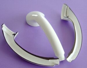
Consider the cup and top appeared of the center and cavity embeds used to mold these parts was already. There are just two potential form opening directions comparative with the part. One mold opening heading is in the hub course of the cup, while the subsequent bearing is the spiral way of the cup.

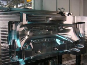
The two striking flat lines demonstrate the area of the splitting plane where the two parts of the addition are part to frame the hole embed (top) and the center supplement (base).

Consider next a similar depression square yet with an outspread form opening course for a bit of the hole embed. For this plan, four striking lines separate the sides from the top and base. Since the metal Core is situated inside the molded part, there is n0 approach to rem0ve the center other than in the part’s hub bearing. The pit embed, in any case, can be isolated into three pieces that move along two unique tomahawks so as to eliminate the molded part.

Of these two structures, the hub mold opening bearing is the least complex plan and is normally liked. Notwithstanding, the subsequent structure is now and then utilized practically speaking since it takes into account a more intricate part configuration just as more alternatives in finding the splitting line. For example, the subsequent structure may be required if a handle were added to the cup or on the off chance that it were important to move the splitting line to an area away from the top lip. This subsequent structure is known as a”split depression mold” and is talked about in more detail.

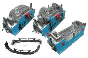
As another model, think about the PC bezel. There are again two potential mold opening headings. The main opening course is in the screen’s review heading, as shown by the segment see. For this situation, the mold area is part by two level lines into a hole embed framing the external surface of the bezel and a center supplement that molds the internal surface and ribs of the bezel. At the point when the center and cavity embeds are isolated as demonstrated by the bolts, the formed bezel can be promptly taken out.

Then again, the depression hinder for the tablet bezel can be part as demonstrated with the three vertical lines. For this situation, the previous pit embed is part into two pieces, coming about again in a split hole mold plan. The two parts of the previous depression embed should now be taken out in sideways ways so as to eliminate the molded part; the form opening course is slanted so as to permit the mold surfaces to isolate from the molded part without inordinate surface rubbing or shearing of highlights on the molded part. This development requires a few extra mold parts to control the moving depression embeds, which add essentially to the expense of form configuration, production, and activity.

This article is from www.injectionmouldchina.com.