Klarm Mould Provides Competitive Molding Service

Attachment head cap screws are the most well-known latches utilized in molds. A %”13 attachment head cap screw is appeared in Fig. 12.32. The essential explanation is that attachment head cap screws have been deliberately planned [12] to enhance the exhibition of the head, strings, and fastener as a framework. In like manner, the attachment head cap screw gives a norm and efficient technique for holding numerous parts along the screw’s hub in injection mould tooling china.

The sizes and burden conveying capacity of attachment head cap screws are identified with their size, material, and medicines. Investigation of standard attachment head screw plans demonstrates that the head tallness is equivalent to the string width, and that the head distance across is around 150% of the string breadth. While the strength of the latch changes to some degree with the coarseness of the string, the rigidity of standard DIN/ISO screws can be genuinely very much assessed by accepting an extreme pressure, ultimate, of 800 MPa duplicated by the cross-sectional zone of the external string width.
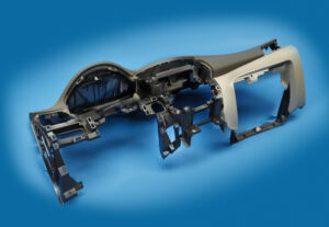
Indicate the size of the attachment head cap screws used to secure the fixed and moving parts of the PC bezel mold. Since this attachment head cap screw is utilized in a basic application of high-precision mould china where disappointment may bring about loss of gear or life, a most dire outcome imaginable is expected.

To begin with, the most extreme mass of the form is assessed accepting a strong square of steel as indicated by the measurements gave in Fig. 12.7.

Then, the most dire outcome imaginable is expected. The most dire outcome imaginable happens when the shape is braced to just one side of the trim machine without the help of the moving platen, which may happen when the form is being introduced in the embellishment machine. Besides, the most dire outcome imaginable will expect that the whole mass of the shape should be upheld by just one fixed screw, which may happen if the other cap screws are not fixed or fixed to lesser sums. The subsequent burden case is appeared in Fig. 12.33.

The applied power on the screw by the form can be assessed by adding the minutes about the finding ring.

Cap screws ought not be depended upon to find form segments given their moderately huge spiral clearances. As recently examined, an obstruction fit ought to be utilized to find one part inside the pocket of another. For equal plates or stacked parts, in any case, dowels or other finding pins ought to be utilized as demonstrated in Fig. 12.34. In this plan, concentric openings are given into the coplanar surfaces of the two plates. A dowel at that point mates with the two openings to find the two parts along the pivot of the dowel.

Assembling differences in the openings’ area, width, and roundness limit the capacity to exactly find the two parts comparative with one another. Condition 12.28 can be utilized for different sorts of fits by fluctuating the cutoff cofficients, C, for the dowel and openings as per global guidelines. Table 1 2.2 gives Coefficients to a locational-leeway fit (LC1), locational-momentary fits (LT1 and LT3), just as the loosest locational-impedance fit (LN1). Locational freedom fits are planned for parts that are commonly fixed yet can be promptly dismantled and reassembled. This fit gives similar request of resistance as strung latches, so isn’t suggested for injection molds since the huge freedom can permit sped up wear of sliding surfaces. Locational-progress fits accommodate more tight control of area, yet with the chance of impedance between the dowel and the opening which upsets the shape get together.

This article is from https://www.injectionmouldchina.com
Warpage Prediction

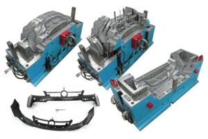
At the point when the embellishment comprises of a solitary shut zone, the material inside the trim is in constant contact with the end goal that any nonuniform shrinkage and stresses over the part may just be settled all through of plane twisting of the part. Injection mould manufacturers in china know that such warpage requires clasping of the plane of the part, which can happen when: (S edge一 S center)> 0.44. (h/W) (h/W)

where h is the divider thickness of the trim, and Scenter and Sedge are the shrinkage rates at the middle and edge of the part, and W is the good ways from the middle to the edge of the embellishment. This clasping examination models the embellishment as an isotropic roundabout plate under uniform outspread edge pressure with a clasping pressure limit of.

As the past warpage investigations have appeared, warpage is brought about by nonuniform shrinkage because of temperature inclinations through the divider thickness of the formed part, pressure angles over the territory of the shaped part, or temperature slopes aCross the zone of the shaped part. These are the most widely recognized reasons for warpage, and have been treated by high-precision mould china with the least complex conceivable examination. In any case, there are different reasons for nonuniform shrinkage including direction and remaining pressure. For additional data, the intrigued form fashioner is alluded to the examination writing.

Sensibly exact warpage forecasts may likewise be gotten with PC recreation as recently talked about. oem/odm largest plastic injection molding companies gives the warpage forecast from PC recreation for the reproduction portrayed for Fig. 10.8. The outcomes recommend that the center of the part will bow down while the left and right sides of the bezel will bow upwards. The purpose behind this conduct is the upper surface of the bezel contains more material, and this upper surface is contracting not exactly the lower part of the ribs.

Given that warpage can be huge contrasted with shrinkage, shape fashioners may decide to make up for warpage by invert biasing the form surfaces dependent on anticipated or noticed warpage. This predisposition is some of the time alluded to as “Kentucky windage,” a shooting term that alludes to the changes a separation shooter must make to represent the breeze [26]. In this manner, Kentucky windage in form configuration alludes to the shaping of the form cavity surfaces with the end goal that after twisting the formed part smoothes to the ideal shape. The utilization of such predisposition isn’t without discussion, since it acquires cost in the forming of shape cavity surfaces while likewise intrinsically changing the warpage and auxiliary conduct of the formed parts. Therefore, it stays a to some degree uncommon practice in oem/odm medical injection mold factory.

Break down warpage accepting that the cup top is focus gated and shaped with ABS at a pressing weight of 66 MPa at the focal point of the part and 0 MPa at the external edge. To assess the warpage, it is first important to compute the shrinkage rates and check the clasping basis. Given the 66 MPa pressing weight and a temperature of 132°C, the straight shrinkage at the middle will be 0.3 1% at the middle. At the edge, the weight of 0 MPa and temperature of 132°C gives a direct shrinkage of 1.66 %. Given that the cup is 2 mm in thickness and 81 mm in breadth, the clasping measure is expressed.

This article is from https://www.injectionmouldchina.com
Coolant Flow Rate

When the cooling time is known to the china injection mold maker, the warmth move rate or”cooling power” expected of the feed system of the double coler mold parts can be determined. The aggregate sum of warmth to be eliminated by the cooling framework, Q mlingsg, is:

where mmoldings is the com bined mass of the formed parts and any related cold sprinters, which can be assessed as the volume of these moldings times their thickness at room temperature.

The cooling power is the characterized as the measure of energy that the must be eliminated every second of cooling time:

Normally, an injection mold has numerous cooling lines. Expecting that the mold is all around planned and each cooling line renoves a similar measure of warmth, at that point the warmth move rate per cooling line might be assessed as:

where nuines is the all out number of cooling lines in the shape. Now, the oem/odm largest plastic injection molding companies ought to perceive that various plan cycles might be important to play out the cooling investigation for various cooling line formats with shifting number of cooling lines.

Any warmth eliminated from the polymer dissolve in the shape hole must be diverted by the coolant. In that capacity, the coolant will increment in temperature as it goes through the shape. This temperature increment isn’t alluring, since the coolant will give less cooling to the last segment of the form through which it streams, If the coolant temperature increment is excessively incredible, at that point warm slopes will emerge over the shaped part, which may prompt differential shrinkage and warpage.

Given a volumetric stream pace of the coolant, V2o the expansion in the coolant

coolant’ temperature along one cooling line is:

The warm properties of some normal coolants are given by plastic mould manufacturers factory. The necessary coolant stream rate can be determined given the permissible increment in the coolant temperature. A commonplace permissible increment in the coolant temperature is 1°C. For an exactness forming application, the permissible increment in the coolant temperature might be 0.1°C. A lot more tight control of the coolant temperature requires a lot higher stream rates, but gives little included advantage given that the form hole surface temperatures will in general change all the more fundamentally between the cooling lines as later talked about.

Subsequent to assessing the necessary coolant stream rate, the plausibility of this worth ought to be checked against the abilities of business form temperature regulators. The determination for an ordinary coolant temperature regulator and an oil temperature regulator are recorded in oem/odm medical mold design factory.

The admissible scope of cooling line distances across would now be able to be resolved dependent on the warmth move and liquid stream limitations. To guarantee satisfactory warmth move from the shape steel to the coolant, tempestuous stream in the coolant is wanted. In the event that the cooling line width is excessively enormous, at that point the direct speed of the water may not be adequate to guarantee violent stream. To guarantee violent stream, the Reynolds number, Re, ought to be more prominent than 4000.

An additionally restricting imperative administers the base cooling line breadth, which is identified with the weight drop needed to compel the coolant through the cooling lines at the necessary volumetric stream rate, The weight drop for water through a cooling line can be assessed from pipe stream.

To figure the base cooling line measurement, the line length and passable weight drop over the cooling line must be known. This data can really be somewhat questionable, since it depends not just upon the design of the cooling lines in the shape, yet additionally whether the cooling lines are funneled in arrangement or equal.

This article is from https://www.injectionmouldchina.com
Cooling Time Estimation

The cooling time is characterized as the measure of time required after the mold is filled for the plastic to turn out to be adequately unbending to launch. The accompanying hypothesis is given to help the assessment of the hypothetical least cooling time for the mould manufacturers factory. By and by, cooling times can be significantly longer than those anticipated by examination for two reasons. To start with, the accompanying examination accepts flawless warmth conduction between the plastic and the form, while there is known to be a considerable warm contact obstruction between two unique materials. The cooling time can be additionally expanded during injection moulding services china by slim holes, which open up between the contracted trim and the form dividers. Second, the cooling time is regularly not driven by the inflexibility of the part, yet rather by quality prerequisites that may require the decay to stretch out the cooling time to accomplish the particulars.

Since there is next to no volumetric dissolve stream of the liquefy after the form filling stage, there is almost no warmth convection. Thus, the exchange of warmth between the plastic and the form is administered by the transient warmth conduction condition:

Here, T is the temperature, t is the time, 2 is the measurement in the thickness bearing, k is the warm conductivity, ρ is the thickness, and Cp is the particular warmth. The warm diffusivity is basically a proportion of a material’s capacity to send heat comparative with its capacity to store heat. For more quick warmth move, form materials with higher warm diffusivity are wanted, however these materials (e. g., aluminum) will in general have lower basic properties than steel as recently plotted in china high-precision mould suppliers.

The transient warmth conduction Eq. 9.2 is a subsequent request, allegorical, incomplete differential condition. Logical answers for transient warmth move have been produced for straightforward calculations, for example, plates and bars. The cooling plastic can be demonstrated as a limited chunk with the temperature of the dissolve at the centerline of the form cavity assessed from an arrangement development:

Taking the initial six terms, m∈[0,5], in the arrangement, a plot of the plastic’s temperature at the centerline is appeared as an element of the cooling time in china industrial injection mold manufacturers. The temperature of the plastic at the focal point of the trim is equivalent to the underlying melt temperature toward the beginning of the cooling cycle. After a short pause, the soften at the focal point of the trim starts to cool. In the end, the plastic will move toward the temperature of the form coolant.

To decide the cooling time, it is important to give some rule that demonstrates when the trim is sufficiently unbending to be shot out from the shape. One sensible methodology is to think about the modulus of the material, which is a proportion of the material to oppose avoidance. The powerful modulus of the material as it cools is appeared on the right-hand hub of injection moulding services. It tends to be seen that as the plastic soften approaches the shape coolant temperature, the modulus additionally moves toward a consistent state esteem. The temperature at which the material has noteworthy unbending nature is identified with the warmth bending temperature (HDT) or the avoidance temperature under burden (DTUL) as portrayed by standard tests, for example, ASTM D648. Condition 9.4 can be settled to give the cooling time as an element of the liquefy, coolant, and discharge temperatures. This article is from https://www.injectionmouldchina.com