Warpage Prediction

At the point when the embellishment comprises of a solitary shut zone, the material inside the trim is in constant contact with the end goal that any nonuniform shrinkage and stresses over the part may just be settled all through of plane twisting of the part. Injection mould manufacturers in china know that such warpage requires clasping of the plane of the part, which can happen when: (S edge一 S center)> 0.44. (h/W) (h/W)

where h is the divider thickness of the trim, and Scenter and Sedge are the shrinkage rates at the middle and edge of the part, and W is the good ways from the middle to the edge of the embellishment. This clasping examination models the embellishment as an isotropic roundabout plate under uniform outspread edge pressure with a clasping pressure limit of.

As the past warpage investigations have appeared, warpage is brought about by nonuniform shrinkage because of temperature inclinations through the divider thickness of the formed part, pressure angles over the territory of the shaped part, or temperature slopes aCross the zone of the shaped part. These are the most widely recognized reasons for warpage, and have been treated by high-precision mould china with the least complex conceivable examination. In any case, there are different reasons for nonuniform shrinkage including direction and remaining pressure. For additional data, the intrigued form fashioner is alluded to the examination writing.

Sensibly exact warpage forecasts may likewise be gotten with PC recreation as recently talked about. oem/odm largest plastic injection molding companies gives the warpage forecast from PC recreation for the reproduction portrayed for Fig. 10.8. The outcomes recommend that the center of the part will bow down while the left and right sides of the bezel will bow upwards. The purpose behind this conduct is the upper surface of the bezel contains more material, and this upper surface is contracting not exactly the lower part of the ribs.
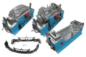
Given that warpage can be huge contrasted with shrinkage, shape fashioners may decide to make up for warpage by invert biasing the form surfaces dependent on anticipated or noticed warpage. This predisposition is some of the time alluded to as “Kentucky windage,” a shooting term that alludes to the changes a separation shooter must make to represent the breeze [26]. In this manner, Kentucky windage in form configuration alludes to the shaping of the form cavity surfaces with the end goal that after twisting the formed part smoothes to the ideal shape. The utilization of such predisposition isn’t without discussion, since it acquires cost in the forming of shape cavity surfaces while likewise intrinsically changing the warpage and auxiliary conduct of the formed parts. Therefore, it stays a to some degree uncommon practice in oem/odm medical injection mold factory.

Break down warpage accepting that the cup top is focus gated and shaped with ABS at a pressing weight of 66 MPa at the focal point of the part and 0 MPa at the external edge. To assess the warpage, it is first important to compute the shrinkage rates and check the clasping basis. Given the 66 MPa pressing weight and a temperature of 132°C, the straight shrinkage at the middle will be 0.3 1% at the middle. At the edge, the weight of 0 MPa and temperature of 132°C gives a direct shrinkage of 1.66 %. Given that the cup is 2 mm in thickness and 81 mm in breadth, the clasping measure is expressed.

This article is from https://www.injectionmouldchina.com
Shrinkage Prediction

PC reenactment is an undeniably basic in plastics item and form plan for china injection molded parts factory, with Autodesk/Moldflow, Core Iech/Moldex3D, and Sigma Engineering/Sigmasoft giving shrinkage assessment to shaped parts. To exhibit the examination for the bezel, Autodesk/Moldlow (Molding Plastics Insight, MPI 2014 [8]) was performed for Cycolac MG47. The isotropic shrinkage rates anticipated by the recreation are given in injection mold services china expecting similar conditions as the earlier investigation: a mid-range liquefy temperature, mid-range coolant temperature, a steady pressing weight of 66 MPa for a period of6 s, and a cooling season of 20 s.

The outcomes demonstrate that the shrinkage changes generally over the form hole. Low shrinkage rates (on the request for 0.3 % and underneath) are anticipated in the slight territories around the edge that freeze at high dissolve pressures. Specifically, the most minimal shrinkage of 0.1 % adjoining the door is anticipated as this region of the hole totally freezes at high soften pressures over 100 MPa while the polymer liquefy is filling the rest of the pit. Moderate shrinkage rates (around 0.6%) are anticipated in the majority of the part, which is more than the 0.31 % shrinkage recently anticipated by the manual investigation. High shrinkage rates (over 1 %) are anticipated close to the furthest limit of fill. The high shrinkage rate toward the finish of fill is because of the way that the material closer the entryway is hardening and forestalling extra polymer liquefy from arriving at the finish of stream to make up for volumetric shrinkage.

The outcomes show a critical issue for the shape planner and the end-client: what shrinkage worth ought to be utilized? In the event that a normal shrinkage of 0.6% is utilized, at that point the part width might be out of detail due to the exorbitant unaccounted shrinkage along the top and base edges.

There are a few unique procedures that can be utilized by the shape planner if nonuniform shrinkage happens. One progressively regular technique, which is upheld by the joint utilization of PC reproduction and CNC machining, is for the form planner to utilize distinctive shrinkage esteems in various parts of the shape. For the PC bezel appeared in oem/odm injection mould factory, the decay may pick a shrinkage estimation of 0.7% for the left and right sides and a shrinkage esteem over 1 % for the top and base sides. In this model, this procedure is moderately simple to utilize and would probably be fruitful since the calculation is generally straightforward. For more unpredictable item calculation with a firmly interconnected surface, in any case, the utilization of non-uniform shrinkage esteems can turn into an intricate and hazardous undertaking.

Another regular way to deal with acquiring tight resistances is to guarantee more uniform shrinkage over the form hole through the expansion of various entryways. By expanding the quantity of entryways for the PC bezel from two to four as appeared in china plastic injection molding, the filling and pressing weights and in this way the shrinkage rate are completely made more uniform over the form pit. In this model, the extra two entryways have diminished the greatest shrinkage from 1.3 % at the focal point of the top edge in Fig. 10.8 to 0.74% at the corners in high precision plastic injection mould factory. Besides, the normal shrinkage in the hole has been decreased from 0.7 % for the twogated shape plan to 0.65% for the four-gated form plan.

Shear Rate

Simultaneous with deciding the gating location(s), the form originator from injection mould manufacturers in china should likewise decide the kind of gate(s$) to be planned. Frequently, the determination of a kind of entryway is evident once the gating areas are indicated. The essential factors that ought to be considered incorporate the sort of sprinter framework, the ideal strategy for de-gating, the permissible degree of shear rates through the entryway, and the subsequent stream that is wanted. To encourage entryway choice, Table 7.1 gives an outline of the sorts and properties of normal doors.

The de gating technique alludes to the utilization of the form activity to de entryway the parts, and doesn’t consider robotized de gating through mechanical technology. The expressed shear rate systems are inexact since they are a component of the entryway measurements and cycle conditions; the degrees of low, moderate, and high generally relate to shear rates on the request for 10, 40, and a 100,000 complementary seconds. At long last, most entryways bring about a spiral stream design out of the door with just the fan, glimmer, and stomach entryways deliberately intended to give straight liquefy stream into the form pit.

In choosing entryway areas and types, the utilization of blended hot and cold sprinters ought to likewise be thought of. Injection mold services china exhibits the utilization of a hot drop with a warm door that takes care of four sub-sprinters and parts masterminded in an outspread format. Such an arrangement could be utilized with a hot sprue bushing to spare material in an ordinary two-plate form, yet is very regular in the hot sprinter molds with an”X” complex setup. Such an application with the plan of Fig. 7.20 would bring about the creation of 16 holes with amazing material turnover in the hot sprinter, low weight drop from the trim machine, and productive material usage in the chilly sprinter.

The shear rates are determined by the recently given conditions to stream in strips and chambers. For reference, the formulae for Newtonian and force law streams are given in Table 7.2. These recipes depend on the volumetric stream rate as opposed to the direct dissolve speed. The explanation is that embellishment measures are arrangement with the volumetric stream rate being indicated, and that the straight dissolve speed of the polymer soften through the entryway isn’t promptly watched. Accordingly, shear rates in doors and sprinters are ordinarily determined as a component of volumetric stream rate.

High-quality double coler mold parts gives the material properties and suggested most extreme shear rates for certain materials. The greatest shear rates ought to be viewed as rough, best case scenario, since as a rule these qualities are taken from general rules for different materials. In all actuality, the greatest shear rates are reliant on the most extreme shear rate, yet additionally the whole warm and mechanical history of the polymer soften. In numerous if not most cases, a lot higher shear rates might be conceivable than the greatest shear rates recorded in Appendix A. Given this problem and the simplicity of expanding the size of entryways, it might be alluring for the shape planner to be”steel safe” and indicate a littler door with the expectation that the form will be tried and the door sizes expanded as important to keep away from inordinate shear rates and tweak the stream.

To ascertain the shear rates, the shape creator must determine some underlying door measurements. For thicker doors having low and moderate shear rates (counting the sprue, edge, tab, fan, and valve entryways), the underlying thickness might be set equivalent to the divider thickness of the embellishment at the location of the entryway. For more slender entryways having moderate and high shear rates (counting the pin-point, streak, stomach, passage, submarine, and warm doors), the underlying thickness might be set equivalent to one a large portion of the divider thickness of the embellishment. Strip-type doors likewise require the detail of the width. For blaze and stomach entryways, the width ought to be set to the edge length along which straight stream is wanted. For other strip-type entryways, the underlying width might be set to double the door thickness; this width can be expanded or diminished to modify the shear rates as vital.

This article is from https://www.injectionmouldchina.com.

Feed System

The essential capacity of the feed system is to pass on the polymer dissolve from the nozzle of the trim machine (where it is plasticized) to the mold cavities (where it will frame an ideal item). In most embellishment applications, the polymer liquefy must cross segments of both the mold stature and the mold width. The crossing of the tallness and width can be practiced by two distinctive mold structures for the feed systems  of china injection mold maker. The feed system mold appeared at left CorreSponds to a two-plate cold sprinter mold structure. The sprue is utilized to manage the polymer soften from the nozzle of the trim machine to the splitting plane. Sprinters in the splitting plane are then used to direct the polymer soften aCIoss the splitting plane to at least one mold cavities.

The subsequent mold plan on the privilege of high-precision mould china relates to a three-plate or hot sprinter mold. In this subsequent structure, the polymer soften is guided over the width and length measurements of the mold by sprinters that are counterbalanced to the splitting plane. Since the sprinters are balanced from the splitting plane, there is huge structure opportunity concerning their directing and gating area. Nonetheless, two arrangements of sprues are required for the polymer soften to navigate the tallness of the mold. Initial, a sprue is expected to manage the polymer liquefy from the n0zzle of the trim machine to the plane of the parallel sprinters. After the soften fl0ws aCross the sprinters, a second arrangement of sprues is expected to direct the liquefy down through a bit of the mold stature to the mold cavities.

As the dissolve engenders through the feed system and cavities, the soften pressure in the infusion molding machine will increment. The feed system must be planned by injection mould manufacturers in china so that there is adequate liquefy strain to drive the polymer dissolve all through the mold cavities. A feed system with an enormous stream obstruction will cause a considerable weight drop during the trim cycle. The fIl0w pace of the polymer liquefy will start to rot when the trim machine arrives at the most extreme admissible injection pressure. On the off chance that the stream rate diminishes considerably before the finish of the mold documenting measure, at that point a short shot or different imperfections are probably going to happen.

The feed system must be intended to cause an adequate constrain drop to dodge short shots, broadened process durations, and different imperfections. The”acceptable” pressure drop through the feed system will rely upon the particulars of the embellishment application, particularly the liquefy constrain needed to fill the pit contrasted with the soften pressure accessible from the trim machine. For instance, a slim divider shaping application may utilize an embellishment machine with 200 MPa of accessible soften pressure. In the event that 150 MPa is needed to fill the depression, at that point the weight drop through the feed system ought not surpass 50 MPa. Nonetheless, if a similar machine was utilized to mold a section requiring just 100 MPa of weight, at that point the feed system could be intended to force a weight drop of 100 MPa.

To precisely indicate the adequate weight drop for the feed system structure by  oem/odm industrial injection moulding design factory, the mold planner should contact the decay to get the embellishment machine’s greatest infusion pressure. The mold fashioner ought to likewise get a gauge of the dissolve compel needed to fill the pit through examination, recreation, model embellishment, or related knowledge. In the event that this data isn’t known, at that point the mold fashioner can expect a most extreme weight drop through the feed arrangement of 50 Mpa (7200 psi). While this weight drop is marginally higher than some industry rehearses, this determination will bring about a steel-safe structure with littler feed system widths and lower material usage.

This article is from https://www.injectionmouldchina.com/