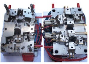
Klarm Mold Provides Qualified Injection Molding

Another basic issue with deep core is inordinate redirection or”core twisting” because of varieties in the soften pressure around the fringe of the center. The variety in liquefy pressure is regularly because of side gating as demonstrated in Fig. 12.27. Notwithstanding, slight varieties in dissolve stream can cause huge twisting in focus gated plans when the centers are thin (e. g., a center length on the request for multiple times the center breadth). The issue is compounded by the way that the core bending impact is self-supporting, which implies that a slight bending of the core encourages more soften stream and strain to the thicker part of the pit and further bowing of the core during injection moulding services china.

Center twisting can be investigated through fitting utilization of bowing conditions. Regularly, the center is held to the moving side of the mold, and the highest point of the center is allowed to twist.
The size of the pressing factor distinction around the center will shift with the calculation of the embellishment application. A more limited center, similar to that appeared in Fig. 12.27, will have a pressing factor contrast that is a critical part of the compel needed to fill the shape (maybe 50 % of the filling pressure). As the center turns out to be longer comparative with its distance across, the pressing factor contrast around the center will turn out to be less contrasted with the pressing factor distinction along its stature (maybe 10% of the filling pressure). Be that as it may, the center avoidance is relative to the fourth force of the center stature, so a little lopsidedness of the liquefy pressing factor can cause a huge redirection.

Normally, core bending in china industrial injection mold manufacturers turns out to be substantially more critical as the center turns out to be more slim. To limit center twisting, the form fashioner ought to use strong centers with an insignificant length to breadth proportion. Whenever the situation allows, slim center pins ought to be interlocked with the fixed side of the form as demonstrated in Fig. 1 2.28. Such interlocking of the center pin lessens the sidelong diversion of the pin to roughly 10% of the redirection for a pin that is upheld on just one end. When interlocking or expanding the size of the center is obliged by the math necessities of the trim application, the shape architect ought to emphatically suggest utilizing a middle entryway at the highest point of the corner or two contradicting doors at the lower part of the center to limit the pressing factor inclination applied on the center.

Figure 12.30 shows the utilization of stream pioneers by china injection mold maker as another way to deal with lessen the center redirection. In this plan, the stream chiefs will help the soften to go down the depression with lower filling pressures. Simultaneously, the dissolve will proliferate into the more slender neighboring segments of the pit and halfway freeze, subsequently keeping the center from avoiding a huge sum regardless of whether critical pressing factor contrasts emerge later in the filling stage. The stream chiefs appeared on the center in Fig.12.29 might be bothersome as bulges on the inward surface of the formed part, particularly for applications including contact with liquids. Thusly, the stream chiefs might be coordinated outwardly surface of the trim as per an assortment of plan arrangements set into the cavity embed. Obviously, center bowing can be extraordinarily decreased by utilizing various entryways on inverse sides of the center pin or by utilizing a ring door at the lower part of the center pin.

In some mold plans of injection mould manufacturers in china, the core is counterbalanced so then the soften is infused, the center pin avoids to deliver a uniform divider thickness. This idea is like providing”windage”to make up for warpage. The achievement of this system will rely upon the nature of the shape configuration, yet will stay touchy to changes in the plastic gum and handling conditions that influence the liquefy pressing factor and stacking on the center pin.

This article is from https://www.injectionmouldchina.com/
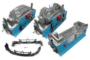
 

Warpage Prediction

At the point when the embellishment comprises of a solitary shut zone, the material inside the trim is in constant contact with the end goal that any nonuniform shrinkage and stresses over the part may just be settled all through of plane twisting of the part. Injection mould manufacturers in china know that such warpage requires clasping of the plane of the part, which can happen when: (S edge一 S center)> 0.44. (h/W) (h/W)

where h is the divider thickness of the trim, and Scenter and Sedge are the shrinkage rates at the middle and edge of the part, and W is the good ways from the middle to the edge of the embellishment. This clasping examination models the embellishment as an isotropic roundabout plate under uniform outspread edge pressure with a clasping pressure limit of.

As the past warpage investigations have appeared, warpage is brought about by nonuniform shrinkage because of temperature inclinations through the divider thickness of the formed part, pressure angles over the territory of the shaped part, or temperature slopes aCross the zone of the shaped part. These are the most widely recognized reasons for warpage, and have been treated by high-precision mould china with the least complex conceivable examination. In any case, there are different reasons for nonuniform shrinkage including direction and remaining pressure. For additional data, the intrigued form fashioner is alluded to the examination writing.

Sensibly exact warpage forecasts may likewise be gotten with PC recreation as recently talked about. oem/odm largest plastic injection molding companies gives the warpage forecast from PC recreation for the reproduction portrayed for Fig. 10.8. The outcomes recommend that the center of the part will bow down while the left and right sides of the bezel will bow upwards. The purpose behind this conduct is the upper surface of the bezel contains more material, and this upper surface is contracting not exactly the lower part of the ribs.

Given that warpage can be huge contrasted with shrinkage, shape fashioners may decide to make up for warpage by invert biasing the form surfaces dependent on anticipated or noticed warpage. This predisposition is some of the time alluded to as “Kentucky windage,” a shooting term that alludes to the changes a separation shooter must make to represent the breeze [26]. In this manner, Kentucky windage in form configuration alludes to the shaping of the form cavity surfaces with the end goal that after twisting the formed part smoothes to the ideal shape. The utilization of such predisposition isn’t without discussion, since it acquires cost in the forming of shape cavity surfaces while likewise intrinsically changing the warpage and auxiliary conduct of the formed parts. Therefore, it stays a to some degree uncommon practice in oem/odm medical injection mold factory.

Break down warpage accepting that the cup top is focus gated and shaped with ABS at a pressing weight of 66 MPa at the focal point of the part and 0 MPa at the external edge. To assess the warpage, it is first important to compute the shrinkage rates and check the clasping basis. Given the 66 MPa pressing weight and a temperature of 132°C, the straight shrinkage at the middle will be 0.3 1% at the middle. At the edge, the weight of 0 MPa and temperature of 132°C gives a direct shrinkage of 1.66 %. Given that the cup is 2 mm in thickness and 81 mm in breadth, the clasping measure is expressed.

This article is from https://www.injectionmouldchina.com

Condition Heating

Given the huge warm mass of the mold and the cooling framework, another procedure for injection moulding services china to control the shape divider is to utilize conduction radiators at or close to the outside of the shape. One plan is appeared in high-quality double coler mold parts; this was created to give a smooth surface completion aside of a frothed plastic item. The shape comprises of a hole embed 12 and a center addition 10, both including an organization of cooling lines 34 and 36 according to regular form plan. A slight metallic sheet 38 adjusts to the outside of the form pit 12, with a flimsy protecting layer of oxide kept between the sheet and the cavity embed. The meager metallic sheet 38 incorporates an initial 40 to convey the plastic liquefy from the sprue 32 to the shape hole 14. Electrical link connections 46 and 48 join the sheet 38 to low voltage, high flow electric links 50 and 52.

Only preceding mold conclusion, the switch 54 is shut to pass a high current through the sheet 38. In this plan, a 0.2 cm thick steel plate was utilized with a length and width of 30 cm and 10 cm, separately. To investigate the warming prerequisites, consider a commonplace formed part with a warmth limit of 2000 J/kg°C, a 3 mm thickness, a liquefy temperature of 240°C, a launch temperature of 100°C, and a process duration of 30 s. For this situation, the warmth load forced on the form by the ABS liquefy is 28 kW/m2; given that the cooling lines are put on different sides of the shape, the cooling power is around 1.4 W/cm2. Accordingly, a 30 cm by 10 cm warming plate must convey in any event 420 W basically to beat the warmth move to the cooling lines before the temperature of the warming plate starts to increment essentially.

It is noticed for china industrial injection mold manufacturers that conduction radiators are broadly accessible with power densities surpassing 250 W/cm2. Such a radiator, whenever set on the outside of a shape pit, could expand a 0.2 cm by 30cm by 10 cm steel plate’s surface temperature by 200°C in 6 s, Attempts have been made to fuse higher force, slim movie warmers straightforwardly into the mold surface. Notwithstanding, such endeavors to consolidate conduction radiators into molds have not been generally fruitful for in any event three reasons. To begin with, the huge, cyclic weight forced on the heater(s) by the polymer dissolve will in general exhaustion the radiators. Second, it is hard to design the heater(s), form cavity, and cooling channels to give the uniform divider temperature needed to convey tasteful surfaces with tight dimensional controls. Third, the radiators are situated between the shape depression and the cooling channels, will in general lessen the pace of warmth move during cooling, thus expand the cooling time. Gauge the energy needed to warm the form center and cavity embeds portrayed in pom moulding parts manufacturers china for a beat cooling measure. To gauge warm energy, the center and depression supplements can be displayed all together of steel with a width and length of 100 mm and a profundity of 200 mm. Given a thickness of steel of 8000 kg/m3, the mass of the additions assessed as 16 kg.

This article is from www.injectionmouldchina.com

Mold Material Selection

As a feature of the mold base plan and acquirement, the materials for the supplements and different segments should likewise be chosen by the mold manufacturer factory. Similarly as there are various plastics reasonable for injection shaping by plastic injection moulders china, there are numerous ferrous and nonferrous metals that are appropriate for use in injection molds.

A portion of the more normal materials and their properties are given. Of every one of these materials, AISI P20 remains the most well-known because of its inescapable commonality and good mix of properties. Nonetheless, P20 is once in a while inappropriately indicated in many embellishment applications since different metals would give better execution, lower form making cost, or lower infusion shaping expenses.

Over the most recent twenty years china mould design services, high-quality aluminum combinations have been embraced in many form structure applications while 3D printed polymers have been utilized for embeds yet with restricted life span.

Class 101 creation molds require the utilization of carbon/apparatus prepares, which are likewise favored for applications with moderate to high embellishment pressures. When the choice to utilize a steel has been made, the steel choice is regularly overwhelmed by concerns identified with wear and scraped area obstruction that is required for the mold’s utilization with fiber-filled tars. On the off chance that scraped spot opposition is definitely not a specific concern, at that point consumption obstruction likewise directs the material choice to a tempered steel, for example, SS420. Something else, instrument prepares, for example, P20 or S7, which are generally simple to machine and clean, are liked.

On the off chance that an embellishment application doesn’t present testing weight and wear prerequisites, at that point nonferrous metals are regularly thought of, particularly for short-run or moderate creation amounts. Airplane grade aluminum 7075-T6 and claim to fame grades created for molds, (for example, Alcoa QC10, Aleris Hokotol, and Vista Duramold) furnish high machining and embellishment efficiency with sensible quality. Product 6061-T6 is a lower-cost choice that gives fairly lower quality yet higher weldability and erosion opposition. For fast prototyping applications with extremely low creation amounts and lower forming pressures of high-precision molds made in china, polymer embeds delivered from a polyjet printing or melded affidavit displaying measure are possible. A portion of the significant properties and compromises of the different mold materials are examined straightaway.

Quality is regularly described by a definitive pressure that a material can suffer before disappointment, or by the yield pressure that can be applied to a material without causing changeless distortion. For infusion molds, nonetheless, neither of these properties ought to be used. Rather, the weariness quality (otherwise called as far as possible pressure) is the measure of pressure that can be consistently applied without causing disappointment.

One issue in basic plan is that the exhaustion conduct varies by material. For most prepares, the exhaustion quality is roughly one-portion of the yield pressure. In any case, aluminum and numerous different materials don’t have a continuance limit. Rather, these materials will inevitably come up short after constant cycling, paying little heed to how little pressure is applied. Therefore, the permissible pressure is characterized after a specific number of cycles (for instance, ten million). Sensible assessments of the admissible worry for weakness are given in Appendix B to various applicant materials; these qualities are later utilized for basic examination.

In light of the fact that mold creators and disintegrates look for changed material properties, there is nobody flawless form material. A typical compromise between the weariness quality and the warm conductivity is appeared in Fig. 4.26 for different materials. All in all, the materials that have the most elevated quality (A2, D2, H13, and P20) have the least warmth move. On the other hand, the materials with the most elevated warmth move (aluminum and copper amalgams, for example, C-18200) have the least quality. No material exists that has a high weariness limit pressure and a high warm diffusivity. P20, the most widely recognized of all mold materials, has great exhaustion quality yet low warm diffusivity, proposing that the form’s presentation might be improved by utilizing other form materials in some trim applications. This article is from www.injectionmouldchina.com.