Klarm Mould Provides Competitive Molding Service

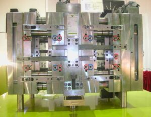
Attachment head cap screws are the most well-known latches utilized in molds. A %”13 attachment head cap screw is appeared in Fig. 12.32. The essential explanation is that attachment head cap screws have been deliberately planned [12] to enhance the exhibition of the head, strings, and fastener as a framework. In like manner, the attachment head cap screw gives a norm and efficient technique for holding numerous parts along the screw’s hub in injection mould tooling china.

The sizes and burden conveying capacity of attachment head cap screws are identified with their size, material, and medicines. Investigation of standard attachment head screw plans demonstrates that the head tallness is equivalent to the string width, and that the head distance across is around 150% of the string breadth. While the strength of the latch changes to some degree with the coarseness of the string, the rigidity of standard DIN/ISO screws can be genuinely very much assessed by accepting an extreme pressure, ultimate, of 800 MPa duplicated by the cross-sectional zone of the external string width.

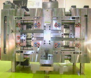
Indicate the size of the attachment head cap screws used to secure the fixed and moving parts of the PC bezel mold. Since this attachment head cap screw is utilized in a basic application of high-precision mould china where disappointment may bring about loss of gear or life, a most dire outcome imaginable is expected.

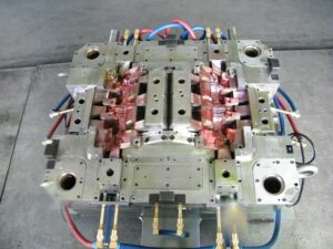
To begin with, the most extreme mass of the form is assessed accepting a strong square of steel as indicated by the measurements gave in Fig. 12.7.

Then, the most dire outcome imaginable is expected. The most dire outcome imaginable happens when the shape is braced to just one side of the trim machine without the help of the moving platen, which may happen when the form is being introduced in the embellishment machine. Besides, the most dire outcome imaginable will expect that the whole mass of the shape should be upheld by just one fixed screw, which may happen if the other cap screws are not fixed or fixed to lesser sums. The subsequent burden case is appeared in Fig. 12.33.

The applied power on the screw by the form can be assessed by adding the minutes about the finding ring.

Cap screws ought not be depended upon to find form segments given their moderately huge spiral clearances. As recently examined, an obstruction fit ought to be utilized to find one part inside the pocket of another. For equal plates or stacked parts, in any case, dowels or other finding pins ought to be utilized as demonstrated in Fig. 12.34. In this plan, concentric openings are given into the coplanar surfaces of the two plates. A dowel at that point mates with the two openings to find the two parts along the pivot of the dowel.

Assembling differences in the openings’ area, width, and roundness limit the capacity to exactly find the two parts comparative with one another. Condition 12.28 can be utilized for different sorts of fits by fluctuating the cutoff cofficients, C, for the dowel and openings as per global guidelines. Table 1 2.2 gives Coefficients to a locational-leeway fit (LC1), locational-momentary fits (LT1 and LT3), just as the loosest locational-impedance fit (LN1). Locational freedom fits are planned for parts that are commonly fixed yet can be promptly dismantled and reassembled. This fit gives similar request of resistance as strung latches, so isn’t suggested for injection molds since the huge freedom can permit sped up wear of sliding surfaces. Locational-progress fits accommodate more tight control of area, yet with the chance of impedance between the dowel and the opening which upsets the shape get together.

This article is from https://www.injectionmouldchina.com

Klarm Mould Offers One-Stop Molding Services

The mold configuration should likewise incorporate clasp to inflexibly attach the numerous parts of the form. There are three sorts of latches generally utilized in molds while injection moulding china.

In the first place, fits are utilized by oem/odm industrial injection moulding design factory to firmly find one segment inside another, for example, a pit or center addition being situated inside a retainer plate. Second, finding pins or dowels are utilized by chinese injection moulding companies to find one parts over another, for example, the ejector lodging to the help plate. These initial two attaching strategies just give securing across the length and width headings of the mold. To attach the mold parts together in the tallness bearing, attachment head cap screws are utilized wherein the screw’s head is held in a form plate and the screw’s strings draw in the segment to be affixed. Every one of these attaching techniques is next broke down.

A”fit”refers to the mating of two segments. A leeway fit alludes to a mating where an ostensible freedom between the surfaces of the two segments. While a leeway fit furnishes for simple get together with insignificant inclusion powers, the freedom between the two segments allows the exact area of segments to stay obscure. Since tight resistances are needed in molds, impedance fits are normally used to find the mold segments.

Obstruction fits happen when the male segment has an ostensible measurement that is bigger than the ostensible element of the female segment, as demonstrated in injection moulding services for a center addition and a retainer plate. Since metals have a high versatile modulus, an inflexible obstruction fit can result when the distinction between the ostensible measurements is little, on the request for 0.01 % of the ostensible measurement. The snugness and inflexibility of the obstruction fit increments with the measure of impedance between the two segments. Sadly, the execution of obstruction fits is blocked by the dimensional varieties forced in the segments machining measures. Therefore, standard systems of fits have been created as far as possible on the elements of the segments.

The fits investigated here depend on a one-sided opening premise and have been changed over from U.S. standard units to metric units. Two of the most widely recognized principles for fitting include”Preferred Limits and Fits for Cylindrical Parts,” ANSI B4.1-1967 (R1999), and”Preferred Metric Limits and Fits” ANSI B4.2-1978 (R1999). ANSI B4.1 is investigated here because of its general straightforwardness and expansive materialness, however the mold originator may adjust to whatever standard is generally fitting. In this strategy, rectangular individuals with width, W, and length, L, are demonstrated as a roundabout part with clear distance across, D.

where C is a coefficient relating to the lower and furthest cutoff for the male or female segment given by worldwide norms. Table 12.1 gives coefficients to locational-obstruction fits (LN1 to LN3) and drive-impedance fits (FN1 to FN3). Locational-impedance fits are utilized when the exactness of area is basic and the parts require sidelong unbending nature. Be that as it may, locational-obstruction fits don’t give huge maintenance power in the stature course, so the parts should be gotten in the tallness heading to another segment through screws or different methods. FN1 to FN3 compare to drive fits with expanding impedance and requiring expanding addition powers. While drive fits give semi perpetual gatherings, mold plans for the most part give screws or different intends to decidedly holding the segments in the tallness heading.

This article is from https://www.injectionmouldchina.com/

Klarm Mold Provides Qualified Injection Molding

Another basic issue with deep core is inordinate redirection or”core twisting” because of varieties in the soften pressure around the fringe of the center. The variety in liquefy pressure is regularly because of side gating as demonstrated in Fig. 12.27. Notwithstanding, slight varieties in dissolve stream can cause huge twisting in focus gated plans when the centers are thin (e. g., a center length on the request for multiple times the center breadth). The issue is compounded by the way that the core bending impact is self-supporting, which implies that a slight bending of the core encourages more soften stream and strain to the thicker part of the pit and further bowing of the core during injection moulding services china.

Center twisting can be investigated through fitting utilization of bowing conditions. Regularly, the center is held to the moving side of the mold, and the highest point of the center is allowed to twist.

The size of the pressing factor distinction around the center will shift with the calculation of the embellishment application. A more limited center, similar to that appeared in Fig. 12.27, will have a pressing factor contrast that is a critical part of the compel needed to fill the shape (maybe 50 % of the filling pressure). As the center turns out to be longer comparative with its distance across, the pressing factor contrast around the center will turn out to be less contrasted with the pressing factor distinction along its stature (maybe 10% of the filling pressure). Be that as it may, the center avoidance is relative to the fourth force of the center stature, so a little lopsidedness of the liquefy pressing factor can cause a huge redirection.

Normally, core bending in china industrial injection mold manufacturers turns out to be substantially more critical as the center turns out to be more slim. To limit center twisting, the form fashioner ought to use strong centers with an insignificant length to breadth proportion. Whenever the situation allows, slim center pins ought to be interlocked with the fixed side of the form as demonstrated in Fig. 1 2.28. Such interlocking of the center pin lessens the sidelong diversion of the pin to roughly 10% of the redirection for a pin that is upheld on just one end. When interlocking or expanding the size of the center is obliged by the math necessities of the trim application, the shape architect ought to emphatically suggest utilizing a middle entryway at the highest point of the corner or two contradicting doors at the lower part of the center to limit the pressing factor inclination applied on the center.

Figure 12.30 shows the utilization of stream pioneers by china injection mold maker as another way to deal with lessen the center redirection. In this plan, the stream chiefs will help the soften to go down the depression with lower filling pressures. Simultaneously, the dissolve will proliferate into the more slender neighboring segments of the pit and halfway freeze, subsequently keeping the center from avoiding a huge sum regardless of whether critical pressing factor contrasts emerge later in the filling stage. The stream chiefs appeared on the center in Fig.12.29 might be bothersome as bulges on the inward surface of the formed part, particularly for applications including contact with liquids. Thusly, the stream chiefs might be coordinated outwardly surface of the trim as per an assortment of plan arrangements set into the cavity embed. Obviously, center bowing can be extraordinarily decreased by utilizing various entryways on inverse sides of the center pin or by utilizing a ring door at the lower part of the center pin.

In some mold plans of injection mould manufacturers in china, the core is counterbalanced so then the soften is infused, the center pin avoids to deliver a uniform divider thickness. This idea is like providing”windage”to make up for warpage. The achievement of this system will rely upon the nature of the shape configuration, yet will stay touchy to changes in the plastic gum and handling conditions that influence the liquefy pressing factor and stacking on the center pin.

This article is from https://www.injectionmouldchina.com/


Warpage Prediction

At the point when the embellishment comprises of a solitary shut zone, the material inside the trim is in constant contact with the end goal that any nonuniform shrinkage and stresses over the part may just be settled all through of plane twisting of the part. Injection mould manufacturers in china know that such warpage requires clasping of the plane of the part, which can happen when: (S edge一 S center)> 0.44. (h/W) (h/W)

where h is the divider thickness of the trim, and Scenter and Sedge are the shrinkage rates at the middle and edge of the part, and W is the good ways from the middle to the edge of the embellishment. This clasping examination models the embellishment as an isotropic roundabout plate under uniform outspread edge pressure with a clasping pressure limit of.

As the past warpage investigations have appeared, warpage is brought about by nonuniform shrinkage because of temperature inclinations through the divider thickness of the formed part, pressure angles over the territory of the shaped part, or temperature slopes aCross the zone of the shaped part. These are the most widely recognized reasons for warpage, and have been treated by high-precision mould china with the least complex conceivable examination. In any case, there are different reasons for nonuniform shrinkage including direction and remaining pressure. For additional data, the intrigued form fashioner is alluded to the examination writing.

Sensibly exact warpage forecasts may likewise be gotten with PC recreation as recently talked about. oem/odm largest plastic injection molding companies gives the warpage forecast from PC recreation for the reproduction portrayed for Fig. 10.8. The outcomes recommend that the center of the part will bow down while the left and right sides of the bezel will bow upwards. The purpose behind this conduct is the upper surface of the bezel contains more material, and this upper surface is contracting not exactly the lower part of the ribs.

Given that warpage can be huge contrasted with shrinkage, shape fashioners may decide to make up for warpage by invert biasing the form surfaces dependent on anticipated or noticed warpage. This predisposition is some of the time alluded to as “Kentucky windage,” a shooting term that alludes to the changes a separation shooter must make to represent the breeze [26]. In this manner, Kentucky windage in form configuration alludes to the shaping of the form cavity surfaces with the end goal that after twisting the formed part smoothes to the ideal shape. The utilization of such predisposition isn’t without discussion, since it acquires cost in the forming of shape cavity surfaces while likewise intrinsically changing the warpage and auxiliary conduct of the formed parts. Therefore, it stays a to some degree uncommon practice in oem/odm medical injection mold factory.

Break down warpage accepting that the cup top is focus gated and shaped with ABS at a pressing weight of 66 MPa at the focal point of the part and 0 MPa at the external edge. To assess the warpage, it is first important to compute the shrinkage rates and check the clasping basis. Given the 66 MPa pressing weight and a temperature of 132°C, the straight shrinkage at the middle will be 0.3 1% at the middle. At the edge, the weight of 0 MPa and temperature of 132°C gives a direct shrinkage of 1.66 %. Given that the cup is 2 mm in thickness and 81 mm in breadth, the clasping measure is expressed.

This article is from https://www.injectionmouldchina.com

Condition Heating

Given the huge warm mass of the mold and the cooling framework, another procedure for injection moulding services china to control the shape divider is to utilize conduction radiators at or close to the outside of the shape. One plan is appeared in high-quality double coler mold parts; this was created to give a smooth surface completion aside of a frothed plastic item. The shape comprises of a hole embed 12 and a center addition 10, both including an organization of cooling lines 34 and 36 according to regular form plan. A slight metallic sheet 38 adjusts to the outside of the form pit 12, with a flimsy protecting layer of oxide kept between the sheet and the cavity embed. The meager metallic sheet 38 incorporates an initial 40 to convey the plastic liquefy from the sprue 32 to the shape hole 14. Electrical link connections 46 and 48 join the sheet 38 to low voltage, high flow electric links 50 and 52.

Only preceding mold conclusion, the switch 54 is shut to pass a high current through the sheet 38. In this plan, a 0.2 cm thick steel plate was utilized with a length and width of 30 cm and 10 cm, separately. To investigate the warming prerequisites, consider a commonplace formed part with a warmth limit of 2000 J/kg°C, a 3 mm thickness, a liquefy temperature of 240°C, a launch temperature of 100°C, and a process duration of 30 s. For this situation, the warmth load forced on the form by the ABS liquefy is 28 kW/m2; given that the cooling lines are put on different sides of the shape, the cooling power is around 1.4 W/cm2. Accordingly, a 30 cm by 10 cm warming plate must convey in any event 420 W basically to beat the warmth move to the cooling lines before the temperature of the warming plate starts to increment essentially.

It is noticed for china industrial injection mold manufacturers that conduction radiators are broadly accessible with power densities surpassing 250 W/cm2. Such a radiator, whenever set on the outside of a shape pit, could expand a 0.2 cm by 30cm by 10 cm steel plate’s surface temperature by 200°C in 6 s, Attempts have been made to fuse higher force, slim movie warmers straightforwardly into the mold surface. Notwithstanding, such endeavors to consolidate conduction radiators into molds have not been generally fruitful for in any event three reasons. To begin with, the huge, cyclic weight forced on the heater(s) by the polymer dissolve will in general exhaustion the radiators. Second, it is hard to design the heater(s), form cavity, and cooling channels to give the uniform divider temperature needed to convey tasteful surfaces with tight dimensional controls. Third, the radiators are situated between the shape depression and the cooling channels, will in general lessen the pace of warmth move during cooling, thus expand the cooling time. Gauge the energy needed to warm the form center and cavity embeds portrayed in pom moulding parts manufacturers china for a beat cooling measure. To gauge warm energy, the center and depression supplements can be displayed all together of steel with a width and length of 100 mm and a profundity of 200 mm. Given a thickness of steel of 8000 kg/m3, the mass of the additions assessed as 16 kg.

This article is from www.injectionmouldchina.com

Cooling Time Estimation

The cooling time is characterized as the measure of time required after the mold is filled for the plastic to turn out to be adequately unbending to launch. The accompanying hypothesis is given to help the assessment of the hypothetical least cooling time for the mould manufacturers factory. By and by, cooling times can be significantly longer than those anticipated by examination for two reasons. To start with, the accompanying examination accepts flawless warmth conduction between the plastic and the form, while there is known to be a considerable warm contact obstruction between two unique materials. The cooling time can be additionally expanded during injection moulding services china by slim holes, which open up between the contracted trim and the form dividers. Second, the cooling time is regularly not driven by the inflexibility of the part, yet rather by quality prerequisites that may require the decay to stretch out the cooling time to accomplish the particulars.

Since there is next to no volumetric dissolve stream of the liquefy after the form filling stage, there is almost no warmth convection. Thus, the exchange of warmth between the plastic and the form is administered by the transient warmth conduction condition:

Here, T is the temperature, t is the time, 2 is the measurement in the thickness bearing, k is the warm conductivity, ρ is the thickness, and Cp is the particular warmth. The warm diffusivity is basically a proportion of a material’s capacity to send heat comparative with its capacity to store heat. For more quick warmth move, form materials with higher warm diffusivity are wanted, however these materials (e. g., aluminum) will in general have lower basic properties than steel as recently plotted in china high-precision mould suppliers.

The transient warmth conduction Eq. 9.2 is a subsequent request, allegorical, incomplete differential condition. Logical answers for transient warmth move have been produced for straightforward calculations, for example, plates and bars. The cooling plastic can be demonstrated as a limited chunk with the temperature of the dissolve at the centerline of the form cavity assessed from an arrangement development:

Taking the initial six terms, m∈[0,5], in the arrangement, a plot of the plastic’s temperature at the centerline is appeared as an element of the cooling time in china industrial injection mold manufacturers. The temperature of the plastic at the focal point of the trim is equivalent to the underlying melt temperature toward the beginning of the cooling cycle. After a short pause, the soften at the focal point of the trim starts to cool. In the end, the plastic will move toward the temperature of the form coolant.

To decide the cooling time, it is important to give some rule that demonstrates when the trim is sufficiently unbending to be shot out from the shape. One sensible methodology is to think about the modulus of the material, which is a proportion of the material to oppose avoidance. The powerful modulus of the material as it cools is appeared on the right-hand hub of injection moulding services. It tends to be seen that as the plastic soften approaches the shape coolant temperature, the modulus additionally moves toward a consistent state esteem. The temperature at which the material has noteworthy unbending nature is identified with the warmth bending temperature (HDT) or the avoidance temperature under burden (DTUL) as portrayed by standard tests, for example, ASTM D648. Condition 9.4 can be settled to give the cooling time as an element of the liquefy, coolant, and discharge temperatures. This article is from https://www.injectionmouldchina.com

Shear Rate

Simultaneous with deciding the gating location(s), the form originator from injection mould manufacturers in china should likewise decide the kind of gate(s$) to be planned. Frequently, the determination of a kind of entryway is evident once the gating areas are indicated. The essential factors that ought to be considered incorporate the sort of sprinter framework, the ideal strategy for de-gating, the permissible degree of shear rates through the entryway, and the subsequent stream that is wanted. To encourage entryway choice, Table 7.1 gives an outline of the sorts and properties of normal doors.

The de gating technique alludes to the utilization of the form activity to de entryway the parts, and doesn’t consider robotized de gating through mechanical technology. The expressed shear rate systems are inexact since they are a component of the entryway measurements and cycle conditions; the degrees of low, moderate, and high generally relate to shear rates on the request for 10, 40, and a 100,000 complementary seconds. At long last, most entryways bring about a spiral stream design out of the door with just the fan, glimmer, and stomach entryways deliberately intended to give straight liquefy stream into the form pit.

In choosing entryway areas and types, the utilization of blended hot and cold sprinters ought to likewise be thought of. Injection mold services china exhibits the utilization of a hot drop with a warm door that takes care of four sub-sprinters and parts masterminded in an outspread format. Such an arrangement could be utilized with a hot sprue bushing to spare material in an ordinary two-plate form, yet is very regular in the hot sprinter molds with an”X” complex setup. Such an application with the plan of Fig. 7.20 would bring about the creation of 16 holes with amazing material turnover in the hot sprinter, low weight drop from the trim machine, and productive material usage in the chilly sprinter.

The shear rates are determined by the recently given conditions to stream in strips and chambers. For reference, the formulae for Newtonian and force law streams are given in Table 7.2. These recipes depend on the volumetric stream rate as opposed to the direct dissolve speed. The explanation is that embellishment measures are arrangement with the volumetric stream rate being indicated, and that the straight dissolve speed of the polymer soften through the entryway isn’t promptly watched. Accordingly, shear rates in doors and sprinters are ordinarily determined as a component of volumetric stream rate.

High-quality double coler mold parts gives the material properties and suggested most extreme shear rates for certain materials. The greatest shear rates ought to be viewed as rough, best case scenario, since as a rule these qualities are taken from general rules for different materials. In all actuality, the greatest shear rates are reliant on the most extreme shear rate, yet additionally the whole warm and mechanical history of the polymer soften. In numerous if not most cases, a lot higher shear rates might be conceivable than the greatest shear rates recorded in Appendix A. Given this problem and the simplicity of expanding the size of entryways, it might be alluring for the shape planner to be”steel safe” and indicate a littler door with the expectation that the form will be tried and the door sizes expanded as important to keep away from inordinate shear rates and tweak the stream.

To ascertain the shear rates, the shape creator must determine some underlying door measurements. For thicker doors having low and moderate shear rates (counting the sprue, edge, tab, fan, and valve entryways), the underlying thickness might be set equivalent to the divider thickness of the embellishment at the location of the entryway. For more slender entryways having moderate and high shear rates (counting the pin-point, streak, stomach, passage, submarine, and warm doors), the underlying thickness might be set equivalent to one a large portion of the divider thickness of the embellishment. Strip-type doors likewise require the detail of the width. For blaze and stomach entryways, the width ought to be set to the edge length along which straight stream is wanted. For other strip-type entryways, the underlying width might be set to double the door thickness; this width can be expanded or diminished to modify the shear rates as vital.

This article is from https://www.injectionmouldchina.com.

Feed System

The essential capacity of the feed system is to pass on the polymer dissolve from the nozzle of the trim machine (where it is plasticized) to the mold cavities (where it will frame an ideal item). In most embellishment applications, the polymer liquefy must cross segments of both the mold stature and the mold width. The crossing of the tallness and width can be practiced by two distinctive mold structures for the feed systems  of china injection mold maker. The feed system mold appeared at left CorreSponds to a two-plate cold sprinter mold structure. The sprue is utilized to manage the polymer soften from the nozzle of the trim machine to the splitting plane. Sprinters in the splitting plane are then used to direct the polymer soften aCIoss the splitting plane to at least one mold cavities.

The subsequent mold plan on the privilege of high-precision mould china relates to a three-plate or hot sprinter mold. In this subsequent structure, the polymer soften is guided over the width and length measurements of the mold by sprinters that are counterbalanced to the splitting plane. Since the sprinters are balanced from the splitting plane, there is huge structure opportunity concerning their directing and gating area. Nonetheless, two arrangements of sprues are required for the polymer soften to navigate the tallness of the mold. Initial, a sprue is expected to manage the polymer liquefy from the n0zzle of the trim machine to the plane of the parallel sprinters. After the soften fl0ws aCross the sprinters, a second arrangement of sprues is expected to direct the liquefy down through a bit of the mold stature to the mold cavities.

As the dissolve engenders through the feed system and cavities, the soften pressure in the infusion molding machine will increment. The feed system must be planned by injection mould manufacturers in china so that there is adequate liquefy strain to drive the polymer dissolve all through the mold cavities. A feed system with an enormous stream obstruction will cause a considerable weight drop during the trim cycle. The fIl0w pace of the polymer liquefy will start to rot when the trim machine arrives at the most extreme admissible injection pressure. On the off chance that the stream rate diminishes considerably before the finish of the mold documenting measure, at that point a short shot or different imperfections are probably going to happen.

The feed system must be intended to cause an adequate constrain drop to dodge short shots, broadened process durations, and different imperfections. The”acceptable” pressure drop through the feed system will rely upon the particulars of the embellishment application, particularly the liquefy constrain needed to fill the pit contrasted with the soften pressure accessible from the trim machine. For instance, a slim divider shaping application may utilize an embellishment machine with 200 MPa of accessible soften pressure. In the event that 150 MPa is needed to fill the depression, at that point the weight drop through the feed system ought not surpass 50 MPa. Nonetheless, if a similar machine was utilized to mold a section requiring just 100 MPa of weight, at that point the feed system could be intended to force a weight drop of 100 MPa.

To precisely indicate the adequate weight drop for the feed system structure by  oem/odm industrial injection moulding design factory, the mold planner should contact the decay to get the embellishment machine’s greatest infusion pressure. The mold fashioner ought to likewise get a gauge of the dissolve compel needed to fill the pit through examination, recreation, model embellishment, or related knowledge. In the event that this data isn’t known, at that point the mold fashioner can expect a most extreme weight drop through the feed arrangement of 50 Mpa (7200 psi). While this weight drop is marginally higher than some industry rehearses, this determination will bring about a steel-safe structure with littler feed system widths and lower material usage.

This article is from https://www.injectionmouldchina.com/

to Choose Mould Machine

While choosing a mold base, the mold planner of oem/odm automotives injection molding factory ought to confirm that the mold will fit in the accessible trim machine(s). There are numerous prerequisites that ought to be viewed as while coordinating a mold to an embellishment machine. To start with, the mold should genuinely fit in the machine or moldings equipment china. Maybe the most widely recognized impediment is that the mold won’t fit between the tie bars. The tie bar dividing is effectively quantifiable on an accessible trim machine or can be checked in a machine drawing for a potential embellishment machine. For example, Fig. 4.23 shows the tie bar dividing and jolt design for a Batten field HM320 molding machine. It very well may be seen that the level tie bar separating is 800 mm, and that the vertical tie bar dispersing is 630 mm. This implies the greatest mold width, including cooling plugs, hot sprinter connectors, and so forth, is 800 mm (some moderately little leeway between the mold and the bind bars to accommodate mold addition).

A cross area perspective on a similar machine platens is appeared in Fig. 4.24 with a similar orientation as appeared in Fig. 1.1. In this view, the spout of the embellishment machine enters the stationary platen on the correct side of the drawing. The machine’s moving platen and the ejector unit are on the left half of the drawing. For the mold to be operable in the machine, the mold tallness must be more noteworthy than the demonstrated A measurement and littler than the showed B measurement, or among 350 and 800 mm for this machine. In the event that the mold is littler than 350 mm, at that point the trim machine platen can’t completely close the mold and fabricate clasp weight. On the off chance that the mold is bigger than 800 mm, at that point the mold won’t fit between the tW0 platens when the moving mold platen is completely open.

Regardless of whether the mold fits in the embellishment machine, the trim machine may at present not be operable with the mold. For example, the injection unit of the trim machine in injection mould manufacturers in china must have adequate shot volume and give enough liquefy strain to fill the mold hole with the polymer dissolve. Then again, on the off chance that the injection unit has too huge a shot size, at that point the control of the injection speed might be restricted and the dissolve may corrupt in the barrel of the embellishment machine. For instance, for the Batten field HM320, the greatest shot volume is 490 cc. To furnish soften homogeneity with-out corruption, this machine is undeniably appropriate for molds requiring a shot volume between 120 cc and 250 cC.

The trim machine should likewise give adequate clasp weight to hold the two parts of the mold together while pressurizing the polymer dissolve. For this machine, the brace weight is 3200 kN, which is equivalent to 326 metric tons, 360 English tons, or 720,000 pounds. In the event that the embellishment machine doesn’t give adequate clasp weight, at that point the mold will open during activity and the soften will stream over the splitting plane and shut-offs. On the off chance that the moulding machine gives an excess of weight to a modest mold, in any case, the mold might be harmed by the forced compressive burdens.

This article is from www.injectionmouldchina.com.

Prototyping Cost Assessment in Mould Manufacturing

The prototyping cost assessment strategies were principally created for class 101 injection molds that are proposed by injection molding service china for large scale manufacturing of a great many shaped parts. In numerous applications, there is the need to create form tooling for lower creation volumes or to”bridge” model and creation. For some embellishment applications, the four normal assembling techniques are:

  1. Class 101 creation molds,
  2. Aluminum tooling for moderate volumes,
  3. Model molds made by added substance fabricating with photopolymers of direct metal laser sintering.
  4. Items straightforwardly made by 3D printing through intertwined statement demonstrating, laser sintering, or stereolithography. For every system, the forthright cost, peripheral expense, and absolute creation time as assessed can be a component of various objective creation volumes as an update to earlier work.

Cost assessment by injection mould manufacturers in china is a settled cycle where the genuine costs needed to secure a made item are completely accounted. The exactness of a quote will change dependent fair and square of detail taken in representing all the exercises and costs in assembling, just as the accuracy of the related occasions and expenses.

Once more, the standard structure for the all out creation cost, C, is applied for every one of the elective assembling procedures. The all out creation time can be likewise determined as where tinitial is the underlying lead time to get the initial segment, and tmarginal is the creation time for each extra part. The normal part cost may likewise be assessed .

Two critical issues in the assessment of shape prototyping techniques are (1) the nature of the secured parts and (2) the life span of the model tooling. To start with, model shape infrequently give the surface completion and execution of parts formed from creation tooling. Specifically, 3D printing measures have a limited goal or line width that can bring about unpleasant surfaces that limit the part style and execution. Straightforwardly created parts (by FDM, particular laser sintering, or stereolithography) have a diminished arrangement of evaluations just as fairly substandard properties identified with the trustworthiness of the established materials. Second, model tooling can have a shorter lifetime because of stress-related disappointments related with infusion of the polymer soften or potentially ejection of the shaped plastic parts.

Hence, it is critical to create sensible expense and time gauges for each assembling methodology by china high-precision mould suppliers. It gives some firm quotes to elective methodologies for creation of the shaped bezels. The initial two lines compare to the two-cavity hot sprinter and one cavity cold sprinter shape that were recently dissected. An option is the utilization of printed embeds that were delivered by a poly jet cycle with bright restored sap. This kind of shape embed has a lifetime on the request for 100 trim cycles, so the form embeds must be consistently recreated to accomplish high creation amounts, which prompts a generally high negligible creation cost of $33 and peripheral creation season of 1 h. Then again, the bezels might be legitimately delivered by melded testimony demonstrating or particular laser sintering with a minimal expense of $60 and a minor creation season of 4 h.

This article is from https://www.injectionmouldchina.com/.