Processing

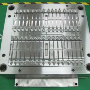
Since the specific shrinkage rate is obscure, a typical practice for shape creators is to plan and assemble the form so it is”steel safe.” In this context,”steel safe” implies that the center and pit embeds are intentionally planned so they can be developed by eliminating existing mold metal if the product measurements are discovered to be modest. For instance, the normal shrinkage rate in an embellishment application might be 0.5%. A”steel safe” plan may use a shrinkage pace of 0.4% on the depression embed, and a 0.6 % shrinkage rate on the center supplement. Such a form plan procedure is appeared in plastic precision injection mould manufacturers china. By planning the depression more modest and the center bigger than needed by the normal shrinkage conduct, the form originator is giving store metal that may promptly be machined to calibrate the components of the shape.

One downside to a”steel safe”mold configuration is that machining will be fundamental in some trim applications paying little mind to the shrinkage conduct that is experienced. The explanation is that by using diverse shrinkage gauges for the center and depression, the ostensible elements of the plastic moldings will be out of resistance. Thus, many shape architects from china injection molded parts factory like to utilize a consistent however mid-range gauge of the shrinkage for the plan of the center and depression embeds, and trust that the decay can change the embellishment cycle to meet quality determinations. Another common”steel safe” practice is to try not to complete basic pit subtleties until after the form is built and tried. By leaving highlights, for example, supervisors, snap fits, and other form pit surfaces in a semi-completed express, the shape originator can finish the plan and execution of these highlights after the shrinkage has been portrayed. While such organized arrangement of highlights in the form configuration stretches the shape fabricate time, the danger during mold advancement is diminished and the resilience of the last moldings can be expanded.

As the investigation has appeared, the volumetric and straight shrinkage are needy upon the soften temperature and weight. Accordingly, disintegrates often depend on change of the embellishment conditions to control the shrinkage and streamline the part measurements [12]. The impact of a few basic preparing conditions on shrinkage is appeared in china standard components for injection mold and are predictable with the noticed shrinkage conduct gave in Table 10.1. The essential factors, true to form, are identified with the weight and temperature of the liquefy in the cavity. Both pressing time and cooling time are critical however small affect shrinkage when adequate pressing and cooling times are utilized by pom moulding products made in china. The coolant temperature has a somewhat more noteworthy impact than Adjustment of the trim cycle gives critical opportunity to alter the ostensible shrinkage rate in the form cavity. To impact the circulation of the shrinkage as a component of position in the form pit, it is conceivable to profile the pressing strain to control the dissolve pressure in the cavity as the soften sets at various areas and times. In particular, a higher pressing weight might be at first utilized toward the beginning of pressing to decrease the shrinkage rate at separations a long way from the door. The pressing weight may then be diminished as the material closer to the door freezes to abstain from over-pressing. To show this methodology, a pressing weight profile was utilized in the mathematical reenactment with the two-gated shape plan.

This article is from https://www.injectionmouldchina.com

Cooling Line Pitch

When the cooling line profundity is chosen, the separation between the cooling lines (known as the”pitch”) is appointed. A more tight pitch, Wine, between cooling lines accommodates quicker and more uniform cooling. Nonetheless, a more tight pitch likewise implies all the more cooling lines and the probability of contentions emerging between the cooling lines and other shape segments. The mold architect from injection mould manufacturers should choose a cooling line pitch that is fitting for the spec ific shaping application utilizing examination.

The temperature expectation of the liquefy during cooling includes the arrangement of an arrangement of illustrative differential conditions. While this is promptly comprehended utilizing the limited component strategy as over, no reasonable systematic treatment has yet been created. This capacity is plotted in newest double coler mold parts for steel and an aluminum form materials. The examination shows that the variety in the warmth transition is under 5% up to a cooling line pitch equivalent to double the cooling line profundity. Thereafter, the variety in heat motion increments significantly and is characteristic of more slow paces of shape cooling and high temperature angles inside the formed part.

To stay away from a critical temperature angle between cooling lines, it is suggested that form planners utilize a cooling line contribute the scope of relying upon the necessities of the application. An item with free resiliences would probably approve of a cooling line pitch equivalent to a few times the cooling line profundity. For more tight resistance applications or for applications requiring quicker process durations or more uniform cooling, a closer separating equivalent to the cooling line profundity is alluring.

Figure 9.5 shows that the utilization of profoundly conductive materials, (for example, aluminum or copper) really expands the variety in heat motion by improving the warmth conduction between the cooling line and the cavity surface. All things considered, the utilization of profoundly conductive materials doesn’t legitimately take into consideration a more extensive pitch and a diminished number of cooling lines. On the off chance that less cooling lines are wanted, at that point this may best be cultivated by choosing a huge cooling line profundity and as yet setting the pitch to twice this sum. Exceptionally conductive form materials would then be able to be used to achieve high paces of warmth move with uniform cooling.

Transient warm recreation was performed for the cup/cover family shape for two form plans having diverse pitch to cooling line profundity proportions. China standard components for injection mold plots the warmth stream from the centerline of the embellishment in the pit to the cooling. In the figure, the lengths of the bolts speak to the overall measure of warmth streaming out of the form depression at that area. As the cooling lines are moved further separated two unfavorable conditions emerge. To start with, the compelling warmth move rate at the form divider is diminished given the limited limit of the cooling lines to eliminate heat. Second, a critical variety in the warmth move rate emerges over the cavity surface.

This variety in the warmth move rate over the hole surface will offer ascent to a slope in the temperature of the moldings at the hour of launch as plotted in oem/odm automatives injection molding design factory. With a tight cooling line pitch, the moldings are catapulted not just with a lesser temperature variety over the trim, yet in addition at an essentially lower temperature. With a wide pitch, the moldings display an a lot higher temperature inclination and an a lot higher temperature.  Curiously, expanding the process duration for the form with the more extensive pitch doesn’t decrease the temperature angles without fundamentally expanding the cooling time to permit the whole shaped part to move toward the coolant temperature.

This article is from https://www.injectionmouldchina.com

Branched Runner

The plan of china injection molded parts factory was explicitly expected for the embellishment of semi-crystalline polymers, for example, polyethylene and polystyrene. Analyses were led with runner measurements of roughly 25 mm and process duration in the region of 60 s; the thickness of the skin was around 6 mm. Obviously, the ideal determination of runner distances across will rely upon the material properties, the soften and form temperatures, and the stream rates and process duration. The utilization of interior radiators and protecting layers, (for example, the air holes, 40a and 40b, around the sprue embeds, 39a and 39b, as appeared in high precision plastic injection mould factory) can give more prominent cycle strength, but with expanded plan intricacy. Maybe due to these handling vulnerabilities, the utilization of protected runner systems has diminished with the commoditization of hot runners. All things being equal, protected runners can give great execution with ease; the creator proposes that form fashioners consider their application in future model trim applications.

A potential issue in”naturally balanced”branched runners in mould manufacture factory is stream irregular characteristics because of warm varieties brought about by the stream and related shearing of the liquefy. Notwithstanding the mathematical equalization of the feed system, it has been seen that parts shaped in cavities might be bigger and heavier relying upon their area in the extended feed system. The stream lopsidedness is made by a non-symmetrical shear appropriation inside the laminar plastic liquefy as it moves through the runner system. In particular, in the feed system there is a dispersion of shear rates and temperatures act0ss the sweep of the runner: a hot polymer liquefy at the focal point of the runner is encircled by a layer of all the more exceptionally sheared, more blazing, and lower-thickness plastic soften. At the point when the laminar soften stream arrives at a branch in the runner system, the lower-thickness dissolve stays in its external position, while the more viscous liquefy at the center is part and streams to the contrary side of the branch, 14. This horizontal variety in consistency will cause a non-uniform stream dispersion at the following downstream branch, 16 and 22.

To determine the stream awkwardness during high precision molds china, it is important to wipe out the parallel consistency variety in the polymer soften. One methodology is the”melt flipper”design that forces a level change only before the branch. In particular, the upstream segment, 100, of Fig. 6.29 relates to the essential runner, 12, of Fig. 6.28 while the downstream segment, 104, relates to the optional runner, 14.


Preceding the branch, a stream diverter, 106, powers the soften upwards into the runner augmentation, 102. At the point when the soften in this manner streams down into the runner, 104, the more thick internal center is coordinated to the side of the runner that is inverse the level change. Since the consistency variety is presently conveyed vertically through the runner, the soften stream is adjusted when the downstream runners branch along the side.

oem/odm automotives injection molding factory gives a plan to a lot of supplements to achieve the level change. The cavity embed, 150, and the center supplement, 156, are set at any important intersection between the upstream and downstream runners. An indented pit, 164, and a jutting center, 162, achieve the level change. Since the consistency variety is just reoriented and not killed, the utilization of different level-changing supplements at successive runner branches will restore the stream imbalances. All the more as of late, research has demonstrated that the stream awkwardness and the capacity to control the soften stream is identified with the liquefy rheology and the preparing conditions. Consequently, extra plans have been created to alter the thickness conveyance in the feed system.


Sucker Pin in Mode Design

Three-plate mold designs from china industrial injection moulding suppliers, frequently use sprue pullers, or”sucker pins,”to follow the chilly runner system to the stripper plate upon the launch of the mold. In this example of injection mold service china, the utilization of sucker pins is expected to give adequate ductile power along the sprue with the end goal that exorbitant pliable anxieties break the door between the sprue and trim. Without the sucker sticks, the chilly runner system would go with the depression plates and be hard to eliminate, since the entryways would even now be joined and there is no instrument given on the a plate to discharge the runner system.

Likewise, mold architects from injection mould manufacturers ought to consider the need of sucker pins during the design of two-plate molds. The essential concern is that the cool runner system may stick to the A portion of the form due to either vacuum attractions to the A plate surface or to the hardening of the plastic dissolve to the machine spout at the head of the sprue. On the off chance that the chilly runner system remains with the fixed side of the mold and all the discharge instruments are on the moving side of the form, at that point the runner system can’t be consequently launched out. The embellishment machine administrator will probably need to postpone the trim machine to physically eliminate the runner system. Besides, in the event that the machine is working on a programmed cycle, at that point the trim machine may attempt to close the form with the runner system still in the mold.

To dodge these issues and improve the dependability of the trim activity, sucker pins might be put at different areas along the feed framework. Maybe the most significant sucker pin is the sprue puller, situated at the base of the sprue, which most successfully serves to disengage the sprue from the machine spout and hold the sprue with the moving side of the mold. In this design by china industrial injection moulding manufacturers, the converse mold at the base of the sprue causes an undercut that holds the sprue. This undercut is later sheared off with the forward actuation of the sprue take out pin.

Other sucker pins might be put at different areas along the cool runner system and, if essential, in the mold pits. The design is very like that of the sprue puller. As for the design, it is re-compacted that the breadth of the sucker be somewhat not exactly the distance across of the related sprinter to keep away from expanded cooling times. The stature and tighten edge of the sucker pin ought to be adequate to pull the sprinter off the fixed side of the form without unnecessary material use Or causing clasping of the related ejector pins upon forward actuation. Common statures and tighten points are one a large portion of the sprinter width and 5 degrees, separately.

The usage justifies a concise conversation. In this usage, an ejector pin has been put underneath the sprinter and opened with a converse mold to hold the sprinter until discharge. Contrasted and the implementation gave at right, the utilization of the opened ejector is a lot more straightforward to machine and simpler to keep up. There are two basic issues, notwithstanding. When high precision plastic making mould suppliers china to start with, the pin as indicated distends marginally into the sprinter area. While this projection won’t fundamentally adjust the stream rates or weight drop through the sprinter, there is a slight possibility that it might incidentally cause an undesired interruption or flimsiness in the stream front. Consequently, it is wanted to adjust the head of the ejector pin with the base of the sprinter. Second, if numerous opened ejector pins are utilized to hold and discharge the runner system, at that point the form fashioner should consider the overall arrangement of the undermining openings. In the event that the arrangement of the openings are not controlled and given aimlessly points, at that point the runner system may accidentally tie to the sucker pins at launch in an arbitrary manner, hampering the appropriation of a fully programmed shaping cycle.

This article is from https://www.injectionmouldchina.com

to Choose Mould Machine

While choosing a mold base, the mold planner of oem/odm automotives injection molding factory ought to confirm that the mold will fit in the accessible trim machine(s). There are numerous prerequisites that ought to be viewed as while coordinating a mold to an embellishment machine. To start with, the mold should genuinely fit in the machine or moldings equipment china. Maybe the most widely recognized impediment is that the mold won’t fit between the tie bars. The tie bar dividing is effectively quantifiable on an accessible trim machine or can be checked in a machine drawing for a potential embellishment machine. For example, Fig. 4.23 shows the tie bar dividing and jolt design for a Batten field HM320 molding machine. It very well may be seen that the level tie bar separating is 800 mm, and that the vertical tie bar dispersing is 630 mm. This implies the greatest mold width, including cooling plugs, hot sprinter connectors, and so forth, is 800 mm (some moderately little leeway between the mold and the bind bars to accommodate mold addition).

A cross area perspective on a similar machine platens is appeared in Fig. 4.24 with a similar orientation as appeared in Fig. 1.1. In this view, the spout of the embellishment machine enters the stationary platen on the correct side of the drawing. The machine’s moving platen and the ejector unit are on the left half of the drawing. For the mold to be operable in the machine, the mold tallness must be more noteworthy than the demonstrated A measurement and littler than the showed B measurement, or among 350 and 800 mm for this machine. In the event that the mold is littler than 350 mm, at that point the trim machine platen can’t completely close the mold and fabricate clasp weight. On the off chance that the mold is bigger than 800 mm, at that point the mold won’t fit between the tW0 platens when the moving mold platen is completely open.

Regardless of whether the mold fits in the embellishment machine, the trim machine may at present not be operable with the mold. For example, the injection unit of the trim machine in injection mould manufacturers in china must have adequate shot volume and give enough liquefy strain to fill the mold hole with the polymer dissolve. Then again, on the off chance that the injection unit has too huge a shot size, at that point the control of the injection speed might be restricted and the dissolve may corrupt in the barrel of the embellishment machine. For instance, for the Batten field HM320, the greatest shot volume is 490 cc. To furnish soften homogeneity with-out corruption, this machine is undeniably appropriate for molds requiring a shot volume between 120 cc and 250 cC.

The trim machine should likewise give adequate clasp weight to hold the two parts of the mold together while pressurizing the polymer dissolve. For this machine, the brace weight is 3200 kN, which is equivalent to 326 metric tons, 360 English tons, or 720,000 pounds. In the event that the embellishment machine doesn’t give adequate clasp weight, at that point the mold will open during activity and the soften will stream over the splitting plane and shut-offs. On the off chance that the moulding machine gives an excess of weight to a modest mold, in any case, the mold might be harmed by the forced compressive burdens.

This article is from www.injectionmouldchina.com.