When the cooling line profundity is chosen, the separation between the cooling lines (known as the”pitch”) is appointed. A more tight pitch, Wine, between cooling lines accommodates quicker and more uniform cooling. Nonetheless, a more tight pitch likewise implies all the more cooling lines and the probability of contentions emerging between the cooling lines and other shape segments. The mold architect from injection mould manufacturers should choose a cooling line pitch that is fitting for the spec ific shaping application utilizing examination.
The temperature expectation of the liquefy during cooling includes the arrangement of an arrangement of illustrative differential conditions. While this is promptly comprehended utilizing the limited component strategy as over, no reasonable systematic treatment has yet been created. This capacity is plotted in newest double coler mold parts for steel and an aluminum form materials. The examination shows that the variety in the warmth transition is under 5% up to a cooling line pitch equivalent to double the cooling line profundity. Thereafter, the variety in heat motion increments significantly and is characteristic of more slow paces of shape cooling and high temperature angles inside the formed part.
To stay away from a critical temperature angle between cooling lines, it is suggested that form planners utilize a cooling line contribute the scope of relying upon the necessities of the application. An item with free resiliences would probably approve of a cooling line pitch equivalent to a few times the cooling line profundity. For more tight resistance applications or for applications requiring quicker process durations or more uniform cooling, a closer separating equivalent to the cooling line profundity is alluring.
Figure 9.5 shows that the utilization of profoundly conductive materials, (for example, aluminum or copper) really expands the variety in heat motion by improving the warmth conduction between the cooling line and the cavity surface. All things considered, the utilization of profoundly conductive materials doesn’t legitimately take into consideration a more extensive pitch and a diminished number of cooling lines. On the off chance that less cooling lines are wanted, at that point this may best be cultivated by choosing a huge cooling line profundity and as yet setting the pitch to twice this sum. Exceptionally conductive form materials would then be able to be used to achieve high paces of warmth move with uniform cooling.
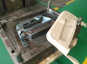
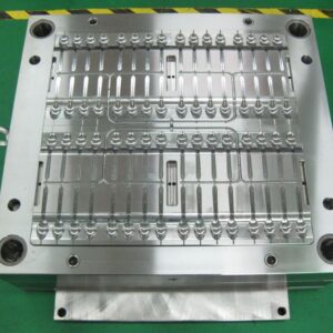
Transient warm recreation was performed for the cup/cover family shape for two form plans having diverse pitch to cooling line profundity proportions. China standard components for injection mold plots the warmth stream from the centerline of the embellishment in the pit to the cooling. In the figure, the lengths of the bolts speak to the overall measure of warmth streaming out of the form depression at that area. As the cooling lines are moved further separated two unfavorable conditions emerge. To start with, the compelling warmth move rate at the form divider is diminished given the limited limit of the cooling lines to eliminate heat. Second, a critical variety in the warmth move rate emerges over the cavity surface.
This variety in the warmth move rate over the hole surface will offer ascent to a slope in the temperature of the moldings at the hour of launch as plotted in oem/odm automatives injection molding design factory. With a tight cooling line pitch, the moldings are catapulted not just with a lesser temperature variety over the trim, yet in addition at an essentially lower temperature. With a wide pitch, the moldings display an a lot higher temperature inclination and an a lot higher temperature. Curiously, expanding the process duration for the form with the more extensive pitch doesn’t decrease the temperature angles without fundamentally expanding the cooling time to permit the whole shaped part to move toward the coolant temperature.
This article is from https://www.injectionmouldchina.com