Collapsible Core

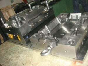
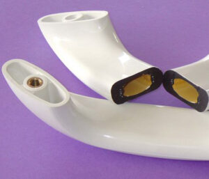
Split pit molds are frequently utilized when the part configuration incorporates complex and undermining outer surfaces. Folding centers are regularly utilized when the part configuration incorporates complex and undermining surfaces on the inside of the part. The plan of a shape which incorporates a folding center is appeared in high precision mould china, which was created to form the top of a doll with an almost uniform divider thickness [12]. The shape depression (14 and 15 together) is framed by two hole embeds 12 and 13, which are burrowed out by a folding center 17. In this plan of automotive mould made in china, the folding center is contained eight sections: 18, 19, 20, 21, 22, 23, 24, and 25. Four of the fragments 18, 19, 20, and 21 are generally three-sided in area and fitted at the corners with a molded external surface in the ideal type of the center. The other four portions 22, 23, 24, and 25 are generally planar in segment and fitted between the corner sections with a shaped external surface to finish the ideal type of the center.

A center pole 37 is situated at the focal point of the center, and forestalls the outspread uprooting of the eight fragments when the folding center is collected. To forestall the pivotal dislodging of the folding center, every one of the eight fragments have a stem 35 with outside strings 35a that draw in the inward strings 39 out of a sleeve 38.

The activity of the folding center depends upon the strings 37b of the center pole 37, and their commitment with the strung way 41 of the sleeve 38. In particular, preceding trim the center bar is turned inside the sleeve so it completely reaches out until its distal (far) end is flush with the finishes of the eight fragments to shape an inflexible center 17. The sleeve with the inflexible center is then positioned in the form cavity and the part is shaped by traditional practice. When the part is hardened, the shape is opened and the formed part is eliminated alongside the center and sleeve. The center pole 37 is then unscrewed from sleeve 38 and eliminated from within the center 17. With no help, the eight portions can implode and be eliminated from within the formed part. The fragments, center bar, and sleeve are then reassembled for the following embellishment cycle.

The folding center plan of oem/odm automotives moulding factory permits complex and undermining highlights to be shaped inside to the formed part. On account of its plan, notwithstanding, a lot of time is needed to collect and dismantle the moving center. To encourage the plan and assembling of molds with folding centers, standard folding center plans have been created and are accessible from various shape base and segment providers. In common plans, the activation of the ejector plate slides the portions along a holding sleeve, which gives a cam activity to implode the center sections during the discharge of the shaped part. This article is from https://www.injectionmouldchina.com/

Induction Heating

Induction heating is another way to deal with expanding the mold divider temperature before shape flling, and is seeing expanded application for micromolding, gleam, and quality. One plan is appeared in mould manufacturers china; this was created to infusion mold fortified thermoplastic composites with prevalent surface gleam and considerably no surface demoldities. T0 lessen energy utilization and warming time and high precision plastic injection mould price, just a little segment of the shape’s surface is specifically warmed by high-recurrence enlistment warming. As appeared in Fig. 9.30, a regular infusion molding machine 3 conveys polymer soften to a shape comprising of a fixed mold half 4 and a versatile shape half 5.

Preceding mold conclusion and flling, a high-recurrence oscillator 1 drives substituting current through an inductance curl (inductor) 2 briefly positioned close the surface(s) of the mold. At the point when a high-recurrence rotating current is gone through the inductor 2, an electromagnetic field is created around the inductor, which along these lines produces swirl flows inside the metal. The obstruction of the shape metal along these lines prompts interior Joule warming of the mold surface. Follows An and B in high precision mould china exhibit the expanded shape surface temperature at areas An and B brought about by induction heating; follows C and D show no underlying impact at area C and D away from the enlistment warming however later increment with the warmth move from the infused polymer soften into the mold pit.

Similarly as with all the recently portrayed methodologies for shape divider temperature control, decays wish to raise the surface temperature of the mold as fast as could reasonably be expected. The warming force through a high recurrence induction heating is relative to the square of the substituting recurrence, the square of the current, and the square of the curl thickness, among different components like china inner part mould manufacturers. In that capacity, the inductors must be painstakingly intended to locally warm the shape surface in a controlled way to keep away from an unwanted temperature circulation. For instance, an inductor was produced using copper container of 5 mm distance across and twisted as a winding with a pitch of 5 mm. The separation between the outside of the metal shape and the inductor was set to 1 cm. Analyses demonstrated that a driving recurrence of 400 kHz yielded a warming force at the mold surface on the request for 1000 W/cm2, which required roughly 10s to expand the outside of the shape by 50°C.

Contrasted with beat cooling and conduction warming, enlistment warming accommodates expanded warming rates with little included shape unpredictability. The essential issue in usage is the plan of the inductor, and specifically the dividing of its curl windings and their connection to the mold surfaces. In the event that the plan is ill-advised, at that point the warming might be restricted to low power levels. Tests showed that a warming force under 100 W/cm2 didn’t altogether build the shape surface temperature and in the long run made the over-burden breaker incite. Then again, when the force yield surpassed 10,000 W/cm2, the pace of the surface temperature increment turned out to be too steep to even consider controlling with the end goal that uniform warming was not, at this point potential; imperfections, for example, gleam abnormalities, sink marks, and so forth were seen with temperature contrasts of more than 50°C over the outside of the mold.

This article is from https://www.injectionmouldchina.com

Interlocking Core

At the point when the part math permits, slim centers with little breadths can be interlocked with the contradicting mold cavity as appeared in Fig. 9.25. Such a plan from injection moulding design china has two preferences. In the first place, the interlocking of the center with the depression offers help for the center and will in general decrease the center flexture as broke down in oem/odm industrial injection mold factory. Second, the interlocking gives a methods by which to pass on coolant from the moving side of the shape, through the center, and to the fixed side of the form. Air is ordinarily utilized as the coolant in such a plan since this coolant will be presented to the shaped part and the climate when the form is opened. While air has a low thickness, which lessens its cooling viability, plan with air channels will give considerably more warmth move than a strong center pin.

There are two regular embellishment circumstances in which there is irrelevant warmth stream from one side of the trim. The first is the long slim center indicated before in china injection mold factory, which depends exclusively on conduction down the hub of the slim pin to move heat from within the embellishment. Since the pin is so thin, there will be very lttle heat move down the length of the pin. Thus, most of the warmth must be moved to the cooling lines in the depression embed.

pom moulding parts made in china plots the warmth motion in a form having a thin center pin. The transition vectors demonstrate that there is some noteworthy warmth move around the centerline of the pin towards the coolant at its base. Nonetheless, the pin’s cross-sectional zone is little to the point that there is an overwhelming outspread warmth motion at the outside of the pin. All in all, the hot plastic liquefy that is contacting the center must exchange a large portion of its warmth entirely through the plastic to the metal and cooling lines of the depression embeds.

As to the cooling of such slim centers, the form creator ought to comprehend that the cooling time will probably be stretched out because of the restricted warmth move to the coolant. A most dire outcome imaginable can be promptly examined by expecting that there is no warmth ransfer deeply. The warmth fIux in this situation is appeared in china high precision mold manufacturer. Since all the warmth must exchange through one side of the trim, the warm conduct is basically equivalent to if two layers of the plastic dissolve were on head of one another. This twofold thickness portrayal is legitimate since the temperature circulation is symmetric over the centerline so there is no related warmth motion.

Uneven warmth stream will likewise happen when forming a plastic layer on head of another material that is ineffectively conductive, as in two-shot (multishot) shaping or overmolding, In these cycles, the primary layer or item may go about as a cover that restricts the warmth stream from the polymer liquefy just injected. As in china mold component machining, the impact of the protecting layer is to confine the warmth stream to only one side of the polymer liquefy. To ascertain the warmth move rates for such uneven warmth streams, mold manufacturing factory might be utilized by subbing double the genuine thickness of the embellishment for the thickness variable, h. The net outcome is that any trim application with an uneven warmth stream will have roughly a four-overlap increment in the cooling time over an embellishment cooled from different sides.

This article is from https://www.injectionmouldchina.com

Edge Gates

The edge gate is a typical sort of door for china mold component machining used to interface a Cold runner to the edge of a form pit. The plan and overhaul of an edge gate for the cup has been recently examined. Another edge gate configuration is appeared. In this plan, the edge door associates with the internal outskirts of the bezel’s supporting edge. Since this door area is interior to the screen get together, any remnant staying after the gate evacuation won’t be seen by the end-client of the trim. In this way, the edge door can and ought to use the full thickness of the adjoining divider segment, and need not be gated underneath the lower surface of the edge.

Contrasted with the pin-point gate, the edge door has enormously diminished shear rates and weight drops. The mold originator of china molds make services can choose the thickness, length, and width esteems as per the requirements of the application. As a rule, the thickness of the edge door, H, ought to be not exactly the divider thickness of the embellishment, however may move toward the thickness of the trim if shear rates are a worry. The width of the gate, W, ought to be not exactly the distance across of the runner yet wide enough to keep away from over the top shear rates. The length of the edge gate ought to be kept to a base, yet long enough to give the embellishment machine administrator access for de-gating with door cutters.

The tab door can be viewed as a variation of the edge gate, wherein a tab is forever added to the trim with the end goal of improved gating. For instance, the edge gate configuration could be tricky since the liquefy streams from the runner into the meager inward casing of the bezel, which can cause untimely freeze-off of the stream and extreme volumetric shrinkage in the encompassing thicker areas. To improve the stream, a tab, rib, or other component is added to the shape depression for the sole motivation behind gating. In this plan from mold manufacturing factory, a rib with a thickness, H, equivalent to the thickness of the ostensible thickness of the part, has been given that associates the runner to the thicker segment of the embellishment outside the slim internal casing, Since the thickness of the tab door is more noteworthy than the thickness of the slender casing, sink will probably create on the top surface. Nonetheless, this issue isn’t huge in this application since this region is covered up by the screen gathering.


Tab gates can be very powerful regarding cost and trim performance. The way in to their adequacy is to set up potential gating territories where their leftovers won’t influence the feel or usefulness of the subsequent moldings. When such gating zones are built up, the form originator should choose whatever tab math and measurements are fitting for the application. Ordinarily the thickness and width are on the request for the ostensible thickness of the part while the length is limited to associate with the nearest accessible runner.

This article is from https://www.injectionmouldchina.com

Runner Volume Calculation

When oem/odm injection mold factory is given the number, lengths, and radii of the feed system, the complete feed system I volume, Vec oral, can be registered as where m is the quantity of various sorts of portions in the feed system,j is a record alluding to a particular kind of sprinter section, N; is the occasions that the sprinter segmentj happens in the feed system, Lj is the length of segmentj, and R, is the span of segmentj. As recently talked about, the form originator ought to limit the absolute volume of the feed system to dodge the creation of abundance material waste or regrind in cool sprinter shape or long habitation times in hot sprinter molds.

The methodology prescribed here is to use imperative based philosophy to legitimately illuminate the base runner system widths given a predetermined limitation on the weight drop. On the off chance that the most extreme weight drop for a segment of the sprinter is indicated as△P。

A trouble with this methodology, notwithstanding, is that the clear thickness, umelt, is a component of the shear rate and the sprinter range. To maintain a strategic distance from iterative assessment of the shear rate and consistency, the force law model can be utilized by oem/odm largest plastic injection molding companies to compute the sweep in a solitary advance.

An issue remains, be that as it may, with respect to what the greatest weight drop ought to be in each section of the feed system. Knowing the detail on the absolute weight drop from the machine nozzle to the depression, different plans can be created to designate the weight drop over each part of the feed system. The easiest methodology is to partition the most extreme weight drop for the whole feed system by the quantity of sections between the spout and the pit. For example, if the polymer dissolve coursed through a sprue, an essential sprinter, and an auxiliary sprinter, and the greatest weight drop for the feed system was 30 MPa, at that point the shape originator could decide to assign a most extreme pressure drop of 10 MPa for every one of the portions of the feed system.

The issue with this methodology, notwithstanding, is that it doesn’t represent the length of each bit of the feed system. An exceptionally short optional sprinter, for example, would be apportioned a similar weight drop as a long essential sprinter. The subsequent plan would be problematic with the breadth being excessively little for the optional sprinter and t0o huge for the essential sprinter.

Another straightforward methodology for oem/odm industrial injection mold factory is to disseminate the weight drop over the feed system with respect to the length of every sprinter section.

where△P: is the most extreme weight drop allotted to sprinter section I with length L, and m is the quantity of sprinter portions between the bay and outlet of the feed system. All things considered, longer sprinter fragments will be permitted a relatively more noteworthy bit of the weight drop through the feed system.

In improving the feed system plan of injection moulding design china, the shape originator needs to accept the stream rates during the filling stage and the normal forced drop. Figure 6.20 additionally shows how the feed system plans will change with the volumetric stream rates during the filling stage. Lower stream rates will bring about lower pres sure drops, which thusly take into account a decrease in the radii and volume of the feed system. Since the real stream rates are controlled by the decay after the form is planned and manufactured, the disintegrate ought to confirm the normal occupy season of the depression with the disintegrate and ascertain the normal stream rates through the feed system. In the event that the stream rates are dubious, at that point the shape fashioner can appraise the direct liquefy speed in the cavity per Eq.5.23 and accept that the stream rate is consistent all through the filling stage.

This article is from https://www.injectionmouldchina.com


Measurements of the Moulding Parts

The length and width measurements are comparably controlled by two necessities in china mould manufacturer. Initially, if a cooling line is required around the outside of the shape hole, at that point the supplements ought to be measured huge enough to oblige such a cooling line. With respect to the tallness recompense, the length and width remittances of three cooling line measurements for every side are run of the mill. Second, the width and length measurements of the additions ought to give side dividers, additionally known as”cheek,” that are sufficiently thick to with-stand the parallel stacking of the dissolve pressure applied as an afterthought dividers of the form cavity. This prerequisite will get commanding (implying that it will surpass the recompense for the cooling lines) for profound parts that need tall side dividers. While the auxiliary structure will be examined in detail, a protected rule is that the thickness of the side divider in the length and width measurement should rise to the profundity of the shape pit.

Figure 4.14 shows a stipend that ought to be added to the length and width of the shape pit to infer the length and width of the center and pit embeds. It tends to be seen that for the PC bezel, the prerequisite of fitting a cooling line will surpass the auxiliary necessity. For the shaped cup, notwithstanding, the supplement length and width measurement are driven by the basic prerequisite.

The center and depression additions would now be able to be made with the recommended measurements. In any case, it is now and then during china molds produce services alluring to modify the cavity embed measurements to give a more productive shape plan. When all is said in done, the length and width measurements of the additions are more basic than the tallness measurement, since these measurements will drive the size of the form base in multi-cavity applications and contribute more to the material and machining costs. Accordingly, these measurements might be diminished fairly by viable cooling and basic structures, which will be additionally examined with later designing investigation.

Figure 4.15 gives the center and pit embeds for the cup. Since the formed part is round, the plan of the center and cavity addition may likewise be round. This shape furnishes an advantage no sweat of assembling, since both the center and pit supplements can be turned on a machine. While the remittances in the hub and spiral measurements are adequate to fit cooling lines, the stipend in the outspread measurement for the pit supplement may not be adequate to withstand the weights applied as an afterthought divider by the liquefy. The side dividers of the pit supplement will in general redirect outward during trim except if it is firmly fit to a pocket in the form base that offers horizontal help.

There is no central prerequisite on the outer state of the center and cavity embeds. While the addition configuration shows round supplements, the form plan for the cup utilized square embeds. Rectangular supplements with or without fileted corners are additionally very normal. The plan of the addition ought to be directed by the state of the formed part, the productivity of the shape structure, and the simplicity of assembling.

The center and depression embeds for the PC bezel are appeared in Fig. 4. 16. For this situation, rectangular additions are structured. The length and width measurements of the supplements have been planned forcefully. While the bezel is very shallow and the supplements are basically satisfactory, the thickness of the encompassing cheek will be scarcely adequate to give cooling around the outskirts of the shape pit while additionally giving space to other form parts.

This article is from www.injectionmouldchina.com.

Different Parts Influence the Mold Costs

There are numerous reasons that formed parts are dismissed in the high precision mold factory. Injection molds factory has good QC and some normal imperfections incorporate short shot, streak, defilement, ill-advised shading match, surface striations because of spread or redden, warpage and other dimensional issues, consume marks, helpless gleam, and others. Since clients request top notch levels on the formed parts they buy, disintegrates frequently inside review and eliminate any inadequate parts that are shaped before shipment to the client.

The expense of these imperfections in the china tooling-building manufacturers can be consolidated into the part cost by assessing the yield. Regular yields fluctuate from 50 to 60 % at fire up for a troublesome application with numerous quality prerequisites to basically 100% for a completely developed ware item. Many cost assessment techniques have been created for formed plastic parts with changing degrees of causality and exactness. The accompanying cost assessment technique of china precision molds manufacturers was created to incorporate the fundamental impacts of the part structure and embellishment measure while being moderately easy to utilize.

A form base is a format or clear shape that is fit to be modified. Alluding to the form plan, the shape base incorporates most of the shape except for the center supplement, cavity embed, hot sprinter, and related parts, for example, ejector pins, uphold columns, and cooling plugs.

The expense of the shape base is a component of the mass of the form and the expense of the steel per unit mass. Measurable cost investigation of shape bases was led and discovered that cost could be firmly demonstrated as where Mmold is the mass of the form base in kg, and Kmold material compares to the expense of the form material per kilogram. Cost information for some generally utilized materials is given. The coefficients were determined by factual relapse of genuine shape base expenses for a few distinctive form bases (from little to enormous size) and four standard form base materials. The gave model has a coefficient of assurance, R2, of 0.922 across 24 distinctive form base statements and gives sensible quotes of the shape base.

Given the different shape measurements, the mass of the form base was assessed factually from relapse of eight diversely measured form bases as While the form measurements are concluded during the shape format configuration measure, they can be at first assessed as where Neavies length and neavitie width are the quantity of holes over the length and width measurements. The factor of 1 .33 is incorporated to accommodate a recompense around the form pits. On the off chance that the format of the shape depressions over the shape is obscure, a lattice design is at first accepted as where the capacity roof adjusts any noninteger number up to the following whole number.

This gauge will in general cause the shape to have bigger size and cost than would really be acknowledged, yet will give in any event a sensible gauge.

The expense of the center and pit embeds is ordinarily the single biggest driver of the all out shape cost. The purposes behind their cost are that they have to contain each mathematical detail of the formed part, are made of extremely hard materials, and are done to a serious extent of precision and quality.

The complete expense of all the hole and center supplements is driven by the expense of each arrangement of additions, Cawitv, increased by the quantity of pit sets, Nnaities, and a markdown factor,favity dscomt, which diminishes the expense per depression with the quantity of cavities.

This article is from https://www.injectionmouldchina.com/.