Klarm Mould Provides Precision Injection Molding

One normal technique for embodiment of fragile parts is pressure shaping as demonstrated in Fig. 13.6 for the creation of a tantalum capacitor. In this interaction, injection molding service china is set as a supplement between two layers of plastic 17 and 18 preceding the form conclusion. The shape configuration gives coordinating with pits 16 and 22 to get the plastic just as scores 21 to get the lead wires 20.

In any trim interaction, the form originator ought to expressly think about the treatment of the shaped parts upon de-embellishment. In the plan of Fig. 13.6, the lower cavity 22 is more profound than the upper depression 16. Furthermore, the lower shape half 11 is given a blaze well 23 for the assortment of any plastic that streams out of the depression during the pressure forming measure. Because of these plan components, the formed part will stay on the lower shape half when the mold opens.

In this pressure shaping interaction, the plastic layers 17 and 18 were cut from sheet stock in a structure to find a way into their comparing cavities while additionally supporting the capacitor 19 and lead wire, 20. It is attractive that the plastic completely contacts the back surface of the shape pits to work with heat move and plastic framing during china injection design service.

Preceding mold conclusion, cartridge radiators in the two form parts 10 and 11 bring the temperature of the shape and plastic layers to over the glass progress temperature of the plastic. When the plastic is mellowed, the shape is gradually shut with low power. As the form gradually shuts, the plastic gradually streams around the capacitor until it is completely epitomized – any abundance plastic in the hole will f1ow out the blaze surface, 24, and into the glimmer well, 23. When the embedded part is completely typified, full clasping power might be applied to the two form parts to make up for shrinkage and accomplish the ideal measurements while the shape is cooled.
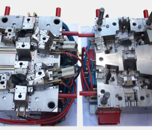
The shape plan of plastic precision injection mould factory has some interesting highlights. In the first place, the depressions secure the addition part in the form to stay away from undesired development brought about by the development of the shape or the progression of the plastic soften during the embellishment interaction. Second, this cycle was explicitly intended to give l0w weight on the embedded part by the controlled warming of the mold and relaxing of the plastic followed by the bracing and cooling of the shape. Given this warming and cooling cycle, the form ought to be painstakingly intended to limit the size and thickness of the plates s0 that energy utilization and process duration are limited. Third, this cycle utilized a lash surface and repository to control lashing of excess plastic; it is plainly attractive to choose a measure of plastic stock that limits the measure of lashing while at the same time guaranteeing a completely filled pit. In this plan, the mating lash surface, 24, on the lower form requires a moderately enormous leeway with mating surface on the upper shape half. In the event that this leeway is too little, the pace of the pressure shaping cycle can be restricted by the progression of the plastic dissolve out of the depression.

This is from https://www.injectionmouldchina.com/

Klarm Mould Offers Precision Molding Service

In the past model, the diversion of the side divider was not an issue. In any case, this issue would almost certainly be huge if the dissolve pressures were higher, the mold cavity was more profound, or the embellishment resistances were more tight. The mold creator from china mould produce services could increment the width of the cheek to decrease the side divider avoidance. In any case, this approach adds huge size and cost to the form. Another option is to use interlocks on the splitting plane close to the edges of the mold to move part of the bowing burden from the fixed portion of the mold to the moving portion of the mold.

Round and rectangular form interlocks are appeared in Fig. 12.20. The two sorts of interlocks ought to be put 0n the splitting plane and as near the form cavities as could be expected. When all is said in done, the rectangular interlock will give more noteworthy protection from diversion because of its bigger size and cross-sectional region across the interlock. However, round interlocks are accessible in more modest sizes and are simpler to introduce in a mold.

A detail perspective on a form configuration consolidating a round interlock is appeared in plastic precision injection mould factory. In this plan, the male interlock is found a way into a through opening in the B plate of the mold. The female interlock is found a way into a visually impaired pocket in the more profound A plate of the mold. The two interlocks firmly fit into the encompassing plates, and are held in the stature course with attachment head cap screws. It is significant that the mold deendorser doesn’t imperil the underlying respectability of the side divider by eliminating abundance mold material while joining the interlocks. At the point when the dissolve pressure is applied 0n the side divider, the interlock will move part of the heap from the A portion of the form to the B half of the mold. The utilization of the interlock adequately doubles the firmness of the side divider, bringing about a splitting of the measure of the side divider diversion.

Since bigger interlocks can convey higher burdens, the biggest interlock ought to be utilized that can be promptly consolidated into the mold plan. In the event that the interlock is presented to a sidelong power, Fateral, applied by the side divider, at that point the shear pressure in the between lock, Tinterlock, can be assessed as:

Tlnterlock= Flnteralock/Alnterlock

where Alnterlock is the cross-sectional region of the interlock at the splitting plane. In the event that the interlock is made of S7 device steel, the plan ought to give a shear pressure less than 300 MPa to stay away from disappointment. It ought to be noticed that temperature contrasts between the moving and fixed mold parts can cause misalignment of the between bolts and sped up wear during mold activity. Ordinary examination during mold support is suggested since this wear can lead straightforwardly to center movements and changes partially measurements.

Gauge the shear pressure in the 19 mm measurement interlock used to help the side mass of the cup cavity.

The essential vulnerability in this investigation is the assessment of the sidelong power applied to the interlock. This assessment of the sidelong power is confounded by the round state of the cup that gives a non-uniform cheek width between the guide pins. Be that as it may, a gauge can be given by accepting that the interlock is presented to the horizontal power from the close by surface of the mold pit. As demonstrated by the brought forth part of oem/odm industrial injection moulding design factory that represents the close by plastic, the powerful zone can be assessed as the item of the interlock width and the depression tallness.

Obviously, the interlock won’t be presented to the entirety of the horizontal power from the soften pressure applied as an afterthought mass of the mold cavity. A moderate gauge is that portion of the power will be conveyed by the interlock. This article is from www.injectionmouldchina.com

Volumetric Shrinkage

As the polymer melt fills, packs, and cools in the form hole, it will be exposed to a scope of liquefy weights and temperatures. Simultaneously, the particular volume of the polymer melt in the cavity will change as needs be. oem/odm 2 shot injection moulding factory gives the melt’s weight, temperature, and explicit volume history during a trim cycle.

china mould design services demonstrates that during plastication, the soften’s temperature and explicit volume increments. During filling, the soften temperature is almost consistent, however an expanded liquefy pressure causes a decrease in the particular volume. During pressing, the material cools with a decrease in weight and temperature, causing a further decrease in the particular volume. After the finish of the pressing stage, no extra material is constrained into the form hole, The melt cools and therapists, causing the soften strain to rot. When the soften pressure arrives at air pressure, the plastic can pull away from the shape divider, with additional volumetric shrinkage making malleable burdens create in the formed part. Toward the finish of the cooling stage, the form opens and any lingering melt pressure is delivered. The part is then shot out and permitted to cool to room temperature.

The particular volume of the plastic after every one of the different embellishment stages is spoken to by china mould manufacturing manufacturers with a scale multiple times the qualities diagramed in plastic injection mold manufacturers china. Each solid shape contains the soften temperature and weight toward the finish of various trim stages, while the size of each 3D square speaks to the particular volume of the melt.

Plastic prototype mould china show that the particular volume subsequent to cooling is 0.97, and the particular volume after launch (when the part has cooled to room temperature) is 0.955. In that capacity, the adjustment in the particular volume of the plastic is – 0.015. This adjustment in the particular volume will lead legitimately to straight shrinkage in the components of the shaped plastic part. The assessment of the volumetric shrinkage toward the finish of the pressing stage is significant to the computation of the volumetric and direct shrinkage.

A sensibly precise gauge of the volumetric shrinkage can be determined if the melt weight and temperature toward the finish of the pressing stage are known. As recently talked about, the soften pressure in the cavity during pressing was assessed as 66 MPa. The temperature of the plastic in the depression is a component of the material properties, form calculation, and handling conditions. In the event that the pressing time is known, at that point the normal liquefy temperature can be assessed as talked about in Chapter 9. Notwithstanding, a more basic methodology is to expect that the soften temperature toward the finish of the pressing stage is equivalent to the no-stream liquefy temperature, which is the temperature at which the polymer has a high consistency. The no-stream temperatures for an assortment of materials are given in Appendix A.

The adjustment in the particular volume can be determined as the adjustment in the particular volume of the plastic toward the finish of the pressing stage and the particular volume of the plastic during end utilization of the shaped part.

Since the no-stream temperature of 405 K is over the change temperature of 386 K,the coefficients for the soften state ought to be utilized. The particular volume toward the finish of the pressing stage (66 MPa and 405 K) can be determined.

This article is from https://www.injectionmouldchina.com

Tunnel

Except for the pin-point entryway utilized with a three-plate mold, all the first gates designs from china mould design services require the expulsion of the feed system from the trim by some post-forming framework (as a rule the administrator). The passage entryway is a typical kind of gate that can be viewed as a variation of the pin-point door. Its essential bit of leeway is that the passage entryway pr0vides for programmed de-gating with the activation of a basic two-plate shape. The plan of a passage entryway for the cover shaping is appeared. Contrasted with the pin point entryway, the progressions have all the earmarks of being corrective with the expansion of certain turns and tightens. These distinctions are irrelevant as for the progression of the plastic dissolve, so the components of the passage entryway ought to be resolved as recently examined to accommodate sensible shear rates and weight drops.

From the outset, the passage gate appears to be fundamentally the same as the pin-point entryway. Nonetheless, they vary altogether in structure and capacity. The capacity of the passage gate can be perceived by looking at the form plan. A cross area through the shut shape with the passage entryway is appeared. The way in to the capacity of the passage entryway is that the passage gate”tunnels” through the pit embed. The embellishment will move away from the depression supplement and remain on the center with the passage door when the shape opens. Simultaneously, the kickoff of the mold powers the passage part of the runner to incidentally stay with the cavity embed. The movement of the center supplement away from the hole embed causes the passage gate to break at its intersection with the embellishment. The embellishment and the feed system would then be able to be launched out as in an ordinary infusion forming measure.

The breadth of the passage entryway at the hole ought to be intended to stay away from unreasonable shear rates and weight drops. For the passage entryway to work dependably, there are two significant points that must be indicated. Initial, an ostensible 45 degree point ought to be kept up between the centerline of the passage door and the splitting plane to take into consideration the transmission of shearing worries to the entryway. Second, the passage door ought to have an included shape point of 20 degrees t0 guarantee that the passage entryway doesn’t stick in the form and that the passage entryway breaks at the intersection with the trim. To guarantee satisfactory auxiliary respectability of the pit undercut, the passage gate ought to be situated in any event three passage measurements off the splitting plane.

The passage gate is a sharp plan since it accommodates programmed de gating without huge venture. The essential danger in application is that the passage entryway might be inappropriately planned or wear with the end goal that lhe runner system doesn’t dependably degate from the trim. T0 help the de-gating of the passage gate from the formed part, the runners ought to be planned with close by sucker pins, to hold the runner system on the center side. In the event that the passage entryways and the runner system stay on the hole side, at that point they can’t be taken out through activation of the discharge system.

There are a few varieties of the passage entryway for the high-precision molds made in china. Similarly as the passage entryway burtows up into the hole embed, the term”submarine”gate alludes to a plan variation where the passage door slides into the center supplements. The activation of the ejector system and the launch of the embellishment of the center at that point demonstration to break the entryway and strip the feed system from the trim. With both passage and submarine entryways, it is likewise conceivable to configuration expanded gates that bend around vertical side dividers to gate onto the inside surfaces of the part. Such an all-inclusive submarine door configuration, otherwise called a”banana”or”cashew”gate,, however such plans represent extra danger as for solid de-gating.

This article is from https://www.injectionmouldchina.com