Plastic Molding Distortion

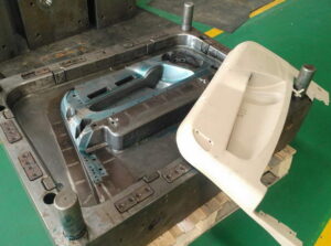
The initial phase in the discharge of the moldings from the mold is to open the shape at least one splitting planes. The mold fashioner should work with the item planner and decay to guarantee that the shape configuration is appropriate and powerful. When all is said in done, the quantity of moving centers ought to be limited by improving the item plan and building up an appropriate shape plan. When moving centers are utilized by china molds design services, they should be planned, whenever the situation allows, to work with the initial activity of the form as opposed to depending on extra actuators and control frameworks.

Now and again the formed part requires a moving center plan that can’t be impelled by the shape opening development. Most current trim machines uphold such”core pull” groupings using advanced signs. After the cooling and plastication stages, when the shape is prepared to open, the trim machine can be customized to give at least one center draw signs to the necessary actuators (commonly pneumatic valves, water driven valves, electric solenoids, or electric engines). The actuators would then be able to withdraw the associated shape parts, which ought to be intended to contact a cutoff switch when completely withdrawn to give a positive input signal that the moving centers are withdrawn and the form is sheltered to open.

The trim machine will normally be modified to postpone the shape opening until all cutoff changes from all center force circuits are stimulated.

For china high precision mold supplier to eliminate the moldings from the shape, discharge powers must be applied to take the moldings off the center surfaces. These discharge powers can be applied by various shape segments including ejector pins, sleeves, sharp edges, lifters, air poppets, stripper plates, and different gadgets. The number, area, and plan of these segments must be created to dependably communicate the powers from the embellishment machine’s take out rod(s) through the launch framework to the plastic moldings. With each discharge cycle, huge shear and compressive powers are applied to the launch framework segments. On the off chance that the segments are inadequately planned, these launch powers may bring about exorbitant shear pressure, compressive pressure, selection, weariness, clasping, and shape disappointment. For instance, the 1se of too hardly any, little pins will cause such high shear stresses to in a real sense poke holes through the shaped section, an imperfection known as push-pin.

Similarly as the launch powers can cause pressure and diversion in the discharge framework segments, the launch powers can likewise cause pressure and redirection in the plastic moldings. To keep away from lasting twisting of the plastic moldings, the number, area, and plan of the ejector parts must be created to apply a low and uniform condition of pressure over the moldings. On the off chance that the ejector power is consistently conveyed across numerous focuses in the form hole, at that point the embellishment will be consistently ejected from the shape with no lasting mutilation.

this article is from https://www.injectionmouldchina.com
Polymer Flow in Mold Making

To break down the polymer stream in china plastic injection molding, it is important to comprehend the connection between the shear pressure, shear rate, and consistency. The shear pressure, T, is a proportion of how much power per unit zone is being applied by the liquid as it streams. The shear rate, I, is a proportion of the rate at which the soften speed changes. The shear pressure is identified with the shear rate through the thickness, 7, which is a proportion of the liquid’s protection from stream.

Consider the stream between a moving plate and a fixed plate appeared in china high precision mold supplier, Expecting that the stream is completely evolved and doesn’t slip at the dividers, at that point a direct speed profile is seen over the liquid with the speed, v, equivalent to zero at the fixed divider and equivalent to V at the moving plate. For a stream between one tationary and one moving equal plate, the shear rate is characterized as the adjustment in the speed through the thickness.

The weight drop brought about by the progression of the polymer dissolve in a channel can be broke down by thinking about the condition of movement. For consistent stream, the whole of the powers m11st ec11al to zero .

Consider the powers acting along the side on the stream in a rectangular direct as appeared in Fig. 5.3. As the stream moves from left to right, there will be a weight drop along the stream with P1 being more noteworthy than P2. This weight drop is being brought about by the gooey stream in the channel that is producing shear stresses, T, against the side dividers. There are two powers on the polymer soften that must adjust. To start with, there is the power because of the weight drop, Fxp, over the length of the liquefy stream. Second, there is the power because of the shear stresses, F, following up on the top and base surfaces along the length. Likening the power because of the weight drop and the power because of the shear stresses Provides Let dP/dL be the weight drop per unit length. Improving at that point gives the accompanying outcome.

To register pressure drop as an element of the thickness, it is important to characterize the consistency as an element of the shear rate and temperature so the shear stresses can be figured.

The expression “rheology” alludes to the investigation of distortion and stream of issue [2, 3]. The term”viscosity” alludes to the obstruction of a liquid as it distorts under. Shear focuses and is characterized by Eq. 5.1 as the shear pressure separated by the shear rate.

The consistency conduct of polymer melts in oem/odm industrial injection moulding factory can be very mind boggling, considerably more so than is frequently refreshing when experts mull over liquefy stream files (MFI). The liquefy stream record, characterized by ASTM D1 238, gauges what number of grams of polymer move through a fine of a predetermined length and width given a predefined measure of weight and time. A higher liquefy stream list typically compares to a lower consistency and improved simplicity of handling. Notwithstanding, the MFI is a solitary point gauge of the thickness and isn’t characteristic of the material conduct over the wide scope of shear rates, temperatures, and weights when it is being formed. Therefore, better thickness models are applied to injection forming by china injection mould maker.

The Cross WLF model [5] is generally known as a competent model of the liquefy thickness, η, as an element of shear rate, I, temperature, T, and weight, P.In this model, no is the”Newtonian limit” in which the consistency moves toward a consistent at exceptionally low shear rates, τ* is a basic feeling of anxiety at which the thickness advances from as far as possible to the force law system, and η is the force law record in the high shear rate system. The type of the Cross model is promptly reasonable since these three boundaries, 7o,τ*, and η, can be assessed legitimately from a log-log plot of the thickness as an element of shear rate as appeared in Fig. 5.4.

In the Cross model, the zero shear thickness, no, is itself a component of temperature, T, and weight, P. The temperature reliance can take numerous structures, including the Arrhenius connection [6]. Another basic model was first portrayed by Williams, landel, and Ferry (WLF) [7] that incorporates pressure reliance through the moving of the glass change temperature, T*. The model boundaries (n, r*, D, D2, D3, A1, A3) are normally controlled by bend fitting exploratory shear-consistency information taken by a narrow rheometer at shear rates from 1 to 10,000 1/s. The material properties for a large number of plastic pitches have been portrayed, and the Cross-WLF model coefficients for some delegate materials are given in Appendix A. The Cross-WLF consistency model for a medium thickness PC is plotted as a component of shear rate for three distinct temperatures in Fig. 5.5. The thickness displays a Newtonian lateau for shear rates up to 100 1/s, at that point changes into a force law system. For a liquefy temperature of 280°C, the thickness diminishes from 350 Pa.sat 100 1/sto 80 Pa.s at 10,000 1/s. Since the thickness is firmly reliant on the shear rate, assessment of the occupying time, dissolve speed, and shear rate are essential to the investigation forecasts. The thickness is likewise a solid capacity of temperature, with the zero shear consistency expanding from 250 Pa.s at 290°C to 660 Pa.s at 270°C. In this way, information on the handling temperature is likewise critical to foreseeing the soften stream and weight. While the Cross WLF model is an exceptionally capable model and is ordinarily utilized in mathematical recreation, it isn’t as valuable in manual illing investigation. The issue is that it is hard to work and not managable to diagnostic arrangement of the weight as an element of the soften stream rate. Hence, a few other thickness models are ordinarily utilized that have moderately straightforward systematic arrangements.

This article is from https://www.injectionmouldchina.com