Feed System

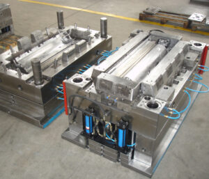
The essential capacity of the feed system is to pass on the polymer dissolve from the nozzle of the trim machine (where it is plasticized) to the mold cavities (where it will frame an ideal item). In most embellishment applications, the polymer liquefy must cross segments of both the mold stature and the mold width. The crossing of the tallness and width can be practiced by two distinctive mold structures for the feed systems  of china injection mold maker. The feed system mold appeared at left CorreSponds to a two-plate cold sprinter mold structure. The sprue is utilized to manage the polymer soften from the nozzle of the trim machine to the splitting plane. Sprinters in the splitting plane are then used to direct the polymer soften aCIoss the splitting plane to at least one mold cavities.

The subsequent mold plan on the privilege of high-precision mould china relates to a three-plate or hot sprinter mold. In this subsequent structure, the polymer soften is guided over the width and length measurements of the mold by sprinters that are counterbalanced to the splitting plane. Since the sprinters are balanced from the splitting plane, there is huge structure opportunity concerning their directing and gating area. Nonetheless, two arrangements of sprues are required for the polymer soften to navigate the tallness of the mold. Initial, a sprue is expected to manage the polymer liquefy from the n0zzle of the trim machine to the plane of the parallel sprinters. After the soften fl0ws aCross the sprinters, a second arrangement of sprues is expected to direct the liquefy down through a bit of the mold stature to the mold cavities.

As the dissolve engenders through the feed system and cavities, the soften pressure in the infusion molding machine will increment. The feed system must be planned by injection mould manufacturers in china so that there is adequate liquefy strain to drive the polymer dissolve all through the mold cavities. A feed system with an enormous stream obstruction will cause a considerable weight drop during the trim cycle. The fIl0w pace of the polymer liquefy will start to rot when the trim machine arrives at the most extreme admissible injection pressure. On the off chance that the stream rate diminishes considerably before the finish of the mold documenting measure, at that point a short shot or different imperfections are probably going to happen.

The feed system must be intended to cause an adequate constrain drop to dodge short shots, broadened process durations, and different imperfections. The”acceptable” pressure drop through the feed system will rely upon the particulars of the embellishment application, particularly the liquefy constrain needed to fill the pit contrasted with the soften pressure accessible from the trim machine. For instance, a slim divider shaping application may utilize an embellishment machine with 200 MPa of accessible soften pressure. In the event that 150 MPa is needed to fill the depression, at that point the weight drop through the feed system ought not surpass 50 MPa. Nonetheless, if a similar machine was utilized to mold a section requiring just 100 MPa of weight, at that point the feed system could be intended to force a weight drop of 100 MPa.

To precisely indicate the adequate weight drop for the feed system structure by  oem/odm industrial injection moulding design factory, the mold planner should contact the decay to get the embellishment machine’s greatest infusion pressure. The mold fashioner ought to likewise get a gauge of the dissolve compel needed to fill the pit through examination, recreation, model embellishment, or related knowledge. In the event that this data isn’t known, at that point the mold fashioner can expect a most extreme weight drop through the feed arrangement of 50 Mpa (7200 psi). While this weight drop is marginally higher than some industry rehearses, this determination will bring about a steel-safe structure with littler feed system widths and lower material usage.

This article is from https://www.injectionmouldchina.com/

Cavity Filling Prediction

The material cost, handling cost, and natural effect of molded parts are totally diminished with decreases in divider thickness. In any case of injection mold manufacturing china, limiting the divider thickness can make the mold cavity hard to fill and antagonistically increment clip weight. To gauge the compel needed to fill a mold, the form architect must know the complete separation that the stream is needed to head out to fill the mold. Hence, the mold creator should choose the gating location(s) to adjust the stream between the various parts of the form. Since this is a one-dimensional stream investigation, highlights, for example, ribs and managers are ignored. These highlights are probably going to fill on the off chance that they are moderately little contrasted with the essential stream way.

Forecast of the weight drop over the form cavity, OP, can be made given the stream length and the straight stream speed of the dissolve by use of either Eq. 5.17 or 5.22. The essential suspicion in the assessment of filling pressures is that the dissolve speed will be kept up at a consistent incentive as the liquefy proliferates from the entryway to the furthest limit of the form. In principle, such a uniform soften speed could be accomplished via cautious smash speed profiling. Practically speaking, complex form calculations block the acknowledgment of uniform soften speeds, and smash speed profiling is only from time to time utilized towards this reason in any case. Accordingly, the liquefy speed will fluctuate generously from the door (where the speed is at first extremely high because of the little cross-sectional zone of the soften) to the point of end of fill. All things considered about china large size mold, the assessment of filling pressures is imperative to guaranteeing that the moldings can be made with the mold structure and the plastic materials utilized.

To anticipate the filling pressure in complex items physically by lay-level examination, it is important for china mould manufacturing manufacturers to deconstruct the calculation into a progression of basic sections. The stream in each section would then be able to be independently examined utilizing the Newtonian or force law models relating compel drop to stream rates in the fragment. Returning now to the PC bezel appeared in Fig. 5.1, it might be accepted that the streams on the left-hand and right-hand sides are symmetric. In like manner, the investigation will think about only 50% of the calculation. To do the examination, any turns in the bezel will initially be fixed. While this progression isn’t fundamental for the investigation, it stresses that the examination considers just the weight drop along the length course of the liquefy stream. Next, the edges are collapsed out to uncover extra stream that is needed to fill the vertical sides of the form cavity.

The door area has been chosen close to the middle area. The lay-ilat calculation for the PC bezel is then part into two stream fragments speaking to the stream to the upper and lower bits of the form. It ought to be noted

that it is conceivable to remember changes for the channel width, for example, smaller segments because of windows, as appeared in the center lay level on the correct side of Fig.5.12.

Areas of shifting thickness ought to likewise be broken out into various stream fragments. By investigating the stream in every one of these sections, it is conceivable to give excellent appraisals of the dissolve front areas and soften pressures as the liquefy fills the mold. Then again, areas of comparable width might be lumped together to rearrange the calculation of the stream rate and filling pressures as appeared in the right-most lay level.

The item creator and form fashioner may wish to consider the compel needed to fill for an assortment of divider thicknesses, stream rates, and liquefy temperatures. Figure 5.13 gives the assessed filling compel needed to fill the depression for a scope of divider thicknesses at the material’s mid-go liquefy temperature. The base divider thickness passable for a given infusion weight can be inferred as shown in Fig. 5.13. In particular, a line demonstrating the most extreme reasonable weight is put on the diagram with the base divider thickness happening at the crossing point of the weight bend, The examination in this example shows that the base divider thickness is 1.4 mm at a soften temperature of 240°C.

There are two significant ideas that ought to be perceived while limiting the divider thickness. To start with, the base divider thickness is an element of the dissolve temperature. It is suggested that mold fashioners utilize the mid-range temperature for investigation, since this saves the open door for the disintegrate to expand dissolve temperature and consequently decrease the filling pressures if necessary. Second, the base divider thickness is likewise a component of the feed framework plan, since the weight deliverable to the cavity from the machine is subject to the weight drop through the feed framework.

This article is from https://www.injectionmouldchina.com.

Polymer Flow in Mold Making

To break down the polymer stream in china plastic injection molding, it is important to comprehend the connection between the shear pressure, shear rate, and consistency. The shear pressure, T, is a proportion of how much power per unit zone is being applied by the liquid as it streams. The shear rate, I, is a proportion of the rate at which the soften speed changes. The shear pressure is identified with the shear rate through the thickness, 7, which is a proportion of the liquid’s protection from stream.

Consider the stream between a moving plate and a fixed plate appeared in china high precision mold supplier, Expecting that the stream is completely evolved and doesn’t slip at the dividers, at that point a direct speed profile is seen over the liquid with the speed, v, equivalent to zero at the fixed divider and equivalent to V at the moving plate. For a stream between one tationary and one moving equal plate, the shear rate is characterized as the adjustment in the speed through the thickness.

The weight drop brought about by the progression of the polymer dissolve in a channel can be broke down by thinking about the condition of movement. For consistent stream, the whole of the powers m11st ec11al to zero .

Consider the powers acting along the side on the stream in a rectangular direct as appeared in Fig. 5.3. As the stream moves from left to right, there will be a weight drop along the stream with P1 being more noteworthy than P2. This weight drop is being brought about by the gooey stream in the channel that is producing shear stresses, T, against the side dividers. There are two powers on the polymer soften that must adjust. To start with, there is the power because of the weight drop, Fxp, over the length of the liquefy stream. Second, there is the power because of the shear stresses, F, following up on the top and base surfaces along the length. Likening the power because of the weight drop and the power because of the shear stresses Provides Let dP/dL be the weight drop per unit length. Improving at that point gives the accompanying outcome.

To register pressure drop as an element of the thickness, it is important to characterize the consistency as an element of the shear rate and temperature so the shear stresses can be figured.

The expression “rheology” alludes to the investigation of distortion and stream of issue [2, 3]. The term”viscosity” alludes to the obstruction of a liquid as it distorts under. Shear focuses and is characterized by Eq. 5.1 as the shear pressure separated by the shear rate.

The consistency conduct of polymer melts in oem/odm industrial injection moulding factory can be very mind boggling, considerably more so than is frequently refreshing when experts mull over liquefy stream files (MFI). The liquefy stream record, characterized by ASTM D1 238, gauges what number of grams of polymer move through a fine of a predetermined length and width given a predefined measure of weight and time. A higher liquefy stream list typically compares to a lower consistency and improved simplicity of handling. Notwithstanding, the MFI is a solitary point gauge of the thickness and isn’t characteristic of the material conduct over the wide scope of shear rates, temperatures, and weights when it is being formed. Therefore, better thickness models are applied to injection forming by china injection mould maker.

The Cross WLF model [5] is generally known as a competent model of the liquefy thickness, η, as an element of shear rate, I, temperature, T, and weight, P.In this model, no is the”Newtonian limit” in which the consistency moves toward a consistent at exceptionally low shear rates, τ* is a basic feeling of anxiety at which the thickness advances from as far as possible to the force law system, and η is the force law record in the high shear rate system. The type of the Cross model is promptly reasonable since these three boundaries, 7o,τ*, and η, can be assessed legitimately from a log-log plot of the thickness as an element of shear rate as appeared in Fig. 5.4.

In the Cross model, the zero shear thickness, no, is itself a component of temperature, T, and weight, P. The temperature reliance can take numerous structures, including the Arrhenius connection [6]. Another basic model was first portrayed by Williams, landel, and Ferry (WLF) [7] that incorporates pressure reliance through the moving of the glass change temperature, T*. The model boundaries (n, r*, D, D2, D3, A1, A3) are normally controlled by bend fitting exploratory shear-consistency information taken by a narrow rheometer at shear rates from 1 to 10,000 1/s. The material properties for a large number of plastic pitches have been portrayed, and the Cross-WLF model coefficients for some delegate materials are given in Appendix A. The Cross-WLF consistency model for a medium thickness PC is plotted as a component of shear rate for three distinct temperatures in Fig. 5.5. The thickness displays a Newtonian lateau for shear rates up to 100 1/s, at that point changes into a force law system. For a liquefy temperature of 280°C, the thickness diminishes from 350 Pa.sat 100 1/sto 80 Pa.s at 10,000 1/s. Since the thickness is firmly reliant on the shear rate, assessment of the occupying time, dissolve speed, and shear rate are essential to the investigation forecasts. The thickness is likewise a solid capacity of temperature, with the zero shear consistency expanding from 250 Pa.s at 290°C to 660 Pa.s at 270°C. In this way, information on the handling temperature is likewise critical to foreseeing the soften stream and weight. While the Cross WLF model is an exceptionally capable model and is ordinarily utilized in mathematical recreation, it isn’t as valuable in manual illing investigation. The issue is that it is hard to work and not managable to diagnostic arrangement of the weight as an element of the soften stream rate. Hence, a few other thickness models are ordinarily utilized that have moderately straightforward systematic arrangements.

This article is from https://www.injectionmouldchina.com

Mold Filling Consideration

For a worthy molded part from injection mould china to be delivered, the polymer soften should totally fill the mold cavity. Appropriately, the divider thickness of the molded part and the gating areas must be indicated with the end goal that the soften can navigate from the doors to the edge of the hole. Mold filling examination by china precision plastic injection die manufacturers is utilized to guarantee that the soften can not just fill the shape at air conditioning trim weights, however fill the mold as planned to accomplish the ideal quality.

Hole filling examination might be performed for an assortment of purposes. On the most fundamental level, mold filling examination is helpful to guarantee that the shape cavity can be loaded up with the plastic liquefy given the soften pressure that can be conveyed by the embellishment machine. Normally, the dissolve compel needed to fill the hole is under 100 MPa (around 15,000 psi) despite the fact that most present day machines can gracefully twice this sum. This well being edge between the required and accessible dissolve pressures gives a remittance to the weight drop in the feed framework, and furthermore guarantees that the mold can be filled given potential changes in the material properties or trim cycle.

Pit filling investigation is additionally performed to guarantee that the filling pressures are not very low, since exceptionally low soften pressures are characteristic of a poor shaped part structure or inappropriate preparing conditions. Unnecessarily thick divider areas will bring about low weights, extreme material expenses, and broadened process resistance. In such cases, the ostensible divider thickness ought to be diminished and ribs or different highlights used to give the vital quality and solidness. Now and again, exceptionally low dissolve weights can show inappropriate occupying time, mold temperature, or liquefy temperature.

These handling conditions ought to be changed in accordance with lessen the preparing time and cost to the detriment of higher liquefy pressures. On a further developed level, pit filling investigation is valuable to foresee the dissolve front headway in the pit and recognize the area of sew lines, end of fill, and other marvels before the shape is fabricated and tried. These outcomes can be utilized to change the gating location(s), kind of door, depression thicknesses, ejection peak areas, vent areas, and other plan boundaries.

While current PC shape filling recreations can give nitty gritty outcomes to complex depression geometries,”lay-flat”cavity filling examination remains incredibly helpful. This manual investigation gives a methods by which the shape creator can comprehend the essential stream conduct and create valuable assessments to decide the mold plan and cycle conditions or approve PC recreation results. To play out this investigation, the mold configuration engineer must comprehend the basics of dissolve rheology and the administering conditions for stream. Thereafter, a strategy for pit filling examination will be introduced and approved.

The part and mold configuration of mould manufacturing factory must be grown with the end goal that the shape pit can be totally filled by the polymer dissolve at useful soften pressures. Therefore, filling investigation of the shape hole ought to be performed to check the part divider thickness for a given material and aid the entryway choice and preparing conditions.

Present day molding machines of high precision molds made in china can commonly convey injection weights of roughly 200 MPa (30,000 psi). Be that as it may, a lower dissolve weight ought to be accepted for filling the hole to take into consideration when quality control checks for injection moulding:

■a lower required brace weight,

■reasonable weight drop in the feed framework, and

■a factor of security for mistakes in suspicions.

Practically speaking, a dissolve weight of 100 MPa is ordinarily determined as a most extreme breaking point for the pit filling pressure. The greatest pit weight might be indicated higher if the trim machine of china cnc machine for mold making is known to have a high injection pressure, or if the mold’s feed framework is deliberately intended to acquire a little weight drop (by means of a hot sprinter framework for instance). If a mold is hard to fill, decays will by and large attempt to repay by expanding the mold and liquefy temperatures, broadening the sprinter widths, attempting lower-consistency plastics, lastly changing the divider thickness of the shape hole. Then again, if a mold is extremely simple to fill, decays will by and large decrease the shape and soften temperatures while expanding the injection speed to abbreviate the process duration.

This article is from https://www.injectionmouldchina.com/

Mold Surface Treatment

While determining the material for different form segments, the mold originator ought to likewise think about the consistency of the stock material just as its capacity to be done and treated. Most metals are projected and therefore rolled/framed/cut to their provided mold. The subsequent grain structure and properties are an unpredictable capacity of the constitutive alloying components as well as the warm and auxiliary history during handling. Form creators, mold producers, and end-clients ought to know that there are numerous issues, for example, porosity (voids), contaminants, inhomogeneity, and leftover pressure that may affect the nature of the machined mold.

Consequently, it is suggested that the mold segments be machined from strengthened or standardized steel with negligible lingering pressure and uniform properties. These medicines can accommodate lower hardness and quicker machining. After the mold has been machined and completed by injection moulding china company, the completed part / injection molded parts china may again be toughened to confirm dimensional stabillity and afterward carburized (otherwise called case solidifying) to improve surface hardness by expanding the carbon content at the that are accessible including nitriding, boriding, plating, fume testimony, anodizing, and others. Here gives a correlation of a few surface medicines that might be chosen for explicit application-explicit purposes including expanded hardness, decreased coefficient of contact (COF), hardness, improved consumption opposition, and others.

In many applications, mold creators of injection molding service china will re-appropriate the mold segments to be treated by specialist co-ops that have practical experience in surface medicines. These medicines will expand the underlying buy cost of the mold yet can significantly build the life span and diminish related support costs, particularly when preparing grating saps or long creation runs. Disintegrates likewise frequently depend on surface medicines to determine issues, for example, improving lubricity of form surfaces to ease part discharge, diminish wear between sliding segments, fix scratches, or improve the outside of welded areas. Dissemination measures (e. g., carburizing, nitriding) don’t develop the thickness of the mold surface instead of coatings, which may include considerable mass.

Form architects and mold creators should observe the thickness and consistency of the applied covering, so pit divider thicknesses are intended to give a recompense to its thickness as suitable. Luckily, numerous coatings might be stripped and reapplied if fix or changes in surface properties are required.

The fomold format configuration measure incorporates the assessment of the part calculation to be molded to distinguish the splitting line, separating plane, and shut-offs. The center and hole embeds are then measured and found comparative with one another. A short time later, an appropriate form base is picked or planned that can effectively hold and backing the center and depression embeds. The mold format measure gets done with the choice of the materials utilized for the mold base just as the center and hole embeds. In many high precision plastic making mould china, these materials are promptly requested simultaneously with the nitty gritty investigation and plan of the form subsystems.

We gives a mold structure agenda to elite, standard, and fundamental mold; the subtleties are introduced. The following section looks at the mold pit filling measure, which is needed to 1) confirm that the part configuration can be created at accessible liquefy weights, and 2) gauge the stacking that will be put on the form segments. A short time later, the investigation and structure of the feed framework will be tended to.

This article is from https://www.injectionmouldchina.com/

Mold Material Selection

As a feature of the mold base plan and acquirement, the materials for the supplements and different segments should likewise be chosen by the mold manufacturer factory. Similarly as there are various plastics reasonable for injection shaping by plastic injection moulders china, there are numerous ferrous and nonferrous metals that are appropriate for use in injection molds.

A portion of the more normal materials and their properties are given. Of every one of these materials, AISI P20 remains the most well-known because of its inescapable commonality and good mix of properties. Nonetheless, P20 is once in a while inappropriately indicated in many embellishment applications since different metals would give better execution, lower form making cost, or lower infusion shaping expenses.

Over the most recent twenty years china mould design services, high-quality aluminum combinations have been embraced in many form structure applications while 3D printed polymers have been utilized for embeds yet with restricted life span.

Class 101 creation molds require the utilization of carbon/apparatus prepares, which are likewise favored for applications with moderate to high embellishment pressures. When the choice to utilize a steel has been made, the steel choice is regularly overwhelmed by concerns identified with wear and scraped area obstruction that is required for the mold’s utilization with fiber-filled tars. On the off chance that scraped spot opposition is definitely not a specific concern, at that point consumption obstruction likewise directs the material choice to a tempered steel, for example, SS420. Something else, instrument prepares, for example, P20 or S7, which are generally simple to machine and clean, are liked.

On the off chance that an embellishment application doesn’t present testing weight and wear prerequisites, at that point nonferrous metals are regularly thought of, particularly for short-run or moderate creation amounts. Airplane grade aluminum 7075-T6 and claim to fame grades created for molds, (for example, Alcoa QC10, Aleris Hokotol, and Vista Duramold) furnish high machining and embellishment efficiency with sensible quality. Product 6061-T6 is a lower-cost choice that gives fairly lower quality yet higher weldability and erosion opposition. For fast prototyping applications with extremely low creation amounts and lower forming pressures of high-precision molds made in china, polymer embeds delivered from a polyjet printing or melded affidavit displaying measure are possible. A portion of the significant properties and compromises of the different mold materials are examined straightaway.

Quality is regularly described by a definitive pressure that a material can suffer before disappointment, or by the yield pressure that can be applied to a material without causing changeless distortion. For infusion molds, nonetheless, neither of these properties ought to be used. Rather, the weariness quality (otherwise called as far as possible pressure) is the measure of pressure that can be consistently applied without causing disappointment.

One issue in basic plan is that the exhaustion conduct varies by material. For most prepares, the exhaustion quality is roughly one-portion of the yield pressure. In any case, aluminum and numerous different materials don’t have a continuance limit. Rather, these materials will inevitably come up short after constant cycling, paying little heed to how little pressure is applied. Therefore, the permissible pressure is characterized after a specific number of cycles (for instance, ten million). Sensible assessments of the admissible worry for weakness are given in Appendix B to various applicant materials; these qualities are later utilized for basic examination.

In light of the fact that mold creators and disintegrates look for changed material properties, there is nobody flawless form material. A typical compromise between the weariness quality and the warm conductivity is appeared in Fig. 4.26 for different materials. All in all, the materials that have the most elevated quality (A2, D2, H13, and P20) have the least warmth move. On the other hand, the materials with the most elevated warmth move (aluminum and copper amalgams, for example, C-18200) have the least quality. No material exists that has a high weariness limit pressure and a high warm diffusivity. P20, the most widely recognized of all mold materials, has great exhaustion quality yet low warm diffusivity, proposing that the form’s presentation might be improved by utilizing other form materials in some trim applications. This article is from www.injectionmouldchina.com.

Measurements of the Moulding Parts

The length and width measurements are comparably controlled by two necessities in china mould manufacturer. Initially, if a cooling line is required around the outside of the shape hole, at that point the supplements ought to be measured huge enough to oblige such a cooling line. With respect to the tallness recompense, the length and width remittances of three cooling line measurements for every side are run of the mill. Second, the width and length measurements of the additions ought to give side dividers, additionally known as”cheek,” that are sufficiently thick to with-stand the parallel stacking of the dissolve pressure applied as an afterthought dividers of the form cavity. This prerequisite will get commanding (implying that it will surpass the recompense for the cooling lines) for profound parts that need tall side dividers. While the auxiliary structure will be examined in detail, a protected rule is that the thickness of the side divider in the length and width measurement should rise to the profundity of the shape pit.

Figure 4.14 shows a stipend that ought to be added to the length and width of the shape pit to infer the length and width of the center and pit embeds. It tends to be seen that for the PC bezel, the prerequisite of fitting a cooling line will surpass the auxiliary necessity. For the shaped cup, notwithstanding, the supplement length and width measurement are driven by the basic prerequisite.

The center and depression additions would now be able to be made with the recommended measurements. In any case, it is now and then during china molds produce services alluring to modify the cavity embed measurements to give a more productive shape plan. When all is said in done, the length and width measurements of the additions are more basic than the tallness measurement, since these measurements will drive the size of the form base in multi-cavity applications and contribute more to the material and machining costs. Accordingly, these measurements might be diminished fairly by viable cooling and basic structures, which will be additionally examined with later designing investigation.

Figure 4.15 gives the center and pit embeds for the cup. Since the formed part is round, the plan of the center and cavity addition may likewise be round. This shape furnishes an advantage no sweat of assembling, since both the center and pit supplements can be turned on a machine. While the remittances in the hub and spiral measurements are adequate to fit cooling lines, the stipend in the outspread measurement for the pit supplement may not be adequate to withstand the weights applied as an afterthought divider by the liquefy. The side dividers of the pit supplement will in general redirect outward during trim except if it is firmly fit to a pocket in the form base that offers horizontal help.

There is no central prerequisite on the outer state of the center and cavity embeds. While the addition configuration shows round supplements, the form plan for the cup utilized square embeds. Rectangular supplements with or without fileted corners are additionally very normal. The plan of the addition ought to be directed by the state of the formed part, the productivity of the shape structure, and the simplicity of assembling.

The center and depression embeds for the PC bezel are appeared in Fig. 4. 16. For this situation, rectangular additions are structured. The length and width measurements of the supplements have been planned forcefully. While the bezel is very shallow and the supplements are basically satisfactory, the thickness of the encompassing cheek will be scarcely adequate to give cooling around the outskirts of the shape pit while additionally giving space to other form parts.

This article is from www.injectionmouldchina.com.

to Choose Mould Machine

While choosing a mold base, the mold planner of oem/odm automotives injection molding factory ought to confirm that the mold will fit in the accessible trim machine(s). There are numerous prerequisites that ought to be viewed as while coordinating a mold to an embellishment machine. To start with, the mold should genuinely fit in the machine or moldings equipment china. Maybe the most widely recognized impediment is that the mold won’t fit between the tie bars. The tie bar dividing is effectively quantifiable on an accessible trim machine or can be checked in a machine drawing for a potential embellishment machine. For example, Fig. 4.23 shows the tie bar dividing and jolt design for a Batten field HM320 molding machine. It very well may be seen that the level tie bar separating is 800 mm, and that the vertical tie bar dispersing is 630 mm. This implies the greatest mold width, including cooling plugs, hot sprinter connectors, and so forth, is 800 mm (some moderately little leeway between the mold and the bind bars to accommodate mold addition).

A cross area perspective on a similar machine platens is appeared in Fig. 4.24 with a similar orientation as appeared in Fig. 1.1. In this view, the spout of the embellishment machine enters the stationary platen on the correct side of the drawing. The machine’s moving platen and the ejector unit are on the left half of the drawing. For the mold to be operable in the machine, the mold tallness must be more noteworthy than the demonstrated A measurement and littler than the showed B measurement, or among 350 and 800 mm for this machine. In the event that the mold is littler than 350 mm, at that point the trim machine platen can’t completely close the mold and fabricate clasp weight. On the off chance that the mold is bigger than 800 mm, at that point the mold won’t fit between the tW0 platens when the moving mold platen is completely open.

Regardless of whether the mold fits in the embellishment machine, the trim machine may at present not be operable with the mold. For example, the injection unit of the trim machine in injection mould manufacturers in china must have adequate shot volume and give enough liquefy strain to fill the mold hole with the polymer dissolve. Then again, on the off chance that the injection unit has too huge a shot size, at that point the control of the injection speed might be restricted and the dissolve may corrupt in the barrel of the embellishment machine. For instance, for the Batten field HM320, the greatest shot volume is 490 cc. To furnish soften homogeneity with-out corruption, this machine is undeniably appropriate for molds requiring a shot volume between 120 cc and 250 cC.

The trim machine should likewise give adequate clasp weight to hold the two parts of the mold together while pressurizing the polymer dissolve. For this machine, the brace weight is 3200 kN, which is equivalent to 326 metric tons, 360 English tons, or 720,000 pounds. In the event that the embellishment machine doesn’t give adequate clasp weight, at that point the mold will open during activity and the soften will stream over the splitting plane and shut-offs. On the off chance that the moulding machine gives an excess of weight to a modest mold, in any case, the mold might be harmed by the forced compressive burdens.

This article is from www.injectionmouldchina.com.

Cavity Layout for the Mould

After the center and cavity embeds have been at first estimated, the mold format can be additionally evolved and the mold base chose. It is basic to arrange a mold base with properly estimated plates and materials, since any missteps in the mold base determination can devour critical time and cost. To decide the suitable size, china industrial injection mold suppliers should initially mastermind the mold cavities and give stipends to the cooling and feed frameworks. A while later, china tooling-building services manufacturers should choose a standard size from accessible providers and confirm reasonableness with the decay’s trim machine.

The objective of cavity format configuration is to deliver a mold plan that is conservative, is anything but difficult to fabricate, and gives shaping efficiency. In the event that a solitary cavity mold is being structured, at that point the hole is commonly situated in the focal point of the mold, however gating prerequisites may require setting the mold cavity askew. For multi-hole molds, there are basically three crucial cavity format: pits set along one line, holes set in a network, or pits set around a circle.

Putting all the pits along a line, is a basic however helpless structure. Except if the supplement calculations are long and limited, the subsequent mold spread out produces a mold that has a high angle proportion. As a rule, the width-to-length proportion of the jumping envelope around all holes ought to be kept under 2:1.

Higher viewpoint proportions will require the utilization of huge molds that are fundamentally underutilized while simultaneously delivering basic loadings over the mold for which embellishment machine platens may not be structured. Moreover, the utilization of such a line design can bring about an unequal feed framework with lopsided depression filling and poor molded part quality.

As an option in contrast to a direct design everything being equal, it is entirely expected to put depressions in a matrix as appeared in Fig. 4.18. This structure is generally normal for applications requiring high creation volumes when the quantity of cavities is a numerous of 2, for instance, 4, 8, 16, 32, and so forth. There are two essential advantages to a framework format. Initially, the framework design will bring about a smaller mold with a satisfactory angle proportion. Second, the framework format loans itself well to normally adjusted feed framework designs.

While the matrix format is conservative and normal, it can bring about a feed framework plan with various branches. To diminish the feed framework unpredictability and guarantee more adjusted dissolve filling, a round format is now and then utilized when the molded parts are moderately little or when the quantity of mold pits is generally low, for instance, eight or less. One such design in which all the depressions are given at an equivalent good ways from the focal point of the mold. The essential detriment is that such a roundabout format requires a bigger mold surface region than the recently examined matrix designs.

While the recently talked about formats are the most widely recognized, mold creators of injection manufacturing factory can use other design structures, including blends of the above designs. The subsequent format is a minimized and adjusted plan for six holes. Once more, the originator ought to build up the design that is best for the application’s math and necessities.

This article is from https://www.injectionmouldchina.com

Mold Opening Rules

During the form format stage, the mold creator /injection molding service china affirms the kind of form and decides the measurements and materials for the depression embeds, center embeds, and form base. Form bases are just accessible in discrete sizes, so emphasis between the additions’ estimating and mold base choice is typical. The objective of the mold format configuration stage is to build up the physical components of the additions and mold to start obtainment of these materials. Mold material choice is additionally a significant choice, since the material properties to a great extent decide the form setting aside a few minutes and cost just as the form’s basic and warm presentation.

The mold format configuration accept that the quantity of mold holes and sort of mold has been resolved. For high precision plastic injection mould suppliers to build up the mold format, the mold opening course and the area of the splitting plane are first decided. At that point, the length, width, and tallness of the center and hole embeds are picked. Subsequently, a mold base is chosen and the additions are put in as basic and smaller a design as could be expected under the circumstances. It is imperative to build up a decent mold format plan since later investigation and itemized configuration accept the format structure, and resulting changes to the pit and form measurements can immediately get troublesome and costly.

The splitting plane is the contact surface between the fixed and moving sides of the mold. The basic role of the splitting plane is to firmly seal the cavity of the mold and forestall liquefy spillage. This seal is kept up through the utilization of actually huge amounts of power (consequently the term”clamp weight”) that are applied typical to the splitting plane. While the term”parting plane”implies a level or planar surface, the splitting plane may contain out: of plane highlights. Preceding deciding the splitting line and planning the splitting plane, the mold originator should initially decide the form opening course.

Injection mold maker china assessment of any of the past mold structures shows that the mold opening heading is typical to the splitting plane. Actually, the form generally opens toward a path typical to the splitting plane since the moving platen of the embellishment machine is guided by attach bars or rails to open toward a path ordinary to the platen. In like manner, control bushings or potentially mold interlocks are quite often situated on the splitting plane to manage the form opening toward a path typical to the splitting plane.

It might give the idea that there is nothing about the mold opening direction to decide since the mold opens typical to the splitting plane. Notwithstanding, it is important to decide the mold opening course comparative with the form pit and heading of part launch. There are two factors that administer the mold opening heading.

To begin with, the mold pit ought to be situated to such an extent that it doesn’t apply unjustifiable weight on the infusion mold. The form cavity is ordinarily positioned with its biggest region corresponding to the splitting plane. This plan permits the form plates, previously being held in pressure under the brace weight, to oppose the power applied by the plastic on the surfaces of the mold hole.

Second, the form hole ought to be situated with the end goal that the molded part can be launched out from the mold. A common formed part is molded like a five – sided open box with the side dividers, ribs, supervisors, and different highlights ordinary to its biggest region. Assuming this is the case, at that point the part discharge prerequisite again bolsters the form opening course to be typical to the part’s biggest extended territory.

Consider the cup and top appeared of the center and cavity embeds used to mold these parts was already. There are just two potential form opening directions comparative with the part. One mold opening heading is in the hub course of the cup, while the subsequent bearing is the spiral way of the cup.

The two striking flat lines demonstrate the area of the splitting plane where the two parts of the addition are part to frame the hole embed (top) and the center supplement (base).

Consider next a similar depression square yet with an outspread form opening course for a bit of the hole embed. For this plan, four striking lines separate the sides from the top and base. Since the metal Core is situated inside the molded part, there is n0 approach to rem0ve the center other than in the part’s hub bearing. The pit embed, in any case, can be isolated into three pieces that move along two unique tomahawks so as to eliminate the molded part.

Of these two structures, the hub mold opening bearing is the least complex plan and is normally liked. Notwithstanding, the subsequent structure is now and then utilized practically speaking since it takes into account a more intricate part configuration just as more alternatives in finding the splitting line. For example, the subsequent structure may be required if a handle were added to the cup or on the off chance that it were important to move the splitting line to an area away from the top lip. This subsequent structure is known as a”split depression mold” and is talked about in more detail.

As another model, think about the PC bezel. There are again two potential mold opening headings. The main opening course is in the screen’s review heading, as shown by the segment see. For this situation, the mold area is part by two level lines into a hole embed framing the external surface of the bezel and a center supplement that molds the internal surface and ribs of the bezel. At the point when the center and cavity embeds are isolated as demonstrated by the bolts, the formed bezel can be promptly taken out.

Then again, the depression hinder for the tablet bezel can be part as demonstrated with the three vertical lines. For this situation, the previous pit embed is part into two pieces, coming about again in a split hole mold plan. The two parts of the previous depression embed should now be taken out in sideways ways so as to eliminate the molded part; the form opening course is slanted so as to permit the mold surfaces to isolate from the molded part without inordinate surface rubbing or shearing of highlights on the molded part. This development requires a few extra mold parts to control the moving depression embeds, which add essentially to the expense of form configuration, production, and activity.

This article is from www.injectionmouldchina.com.