Ejector Gathering

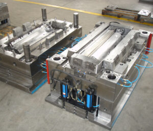
While strung take out poles are moderately easy to plan and work, some shape producers and disintegrates use pressure springs to restore the ejector gathering preceding mold conclusion. One plan is appeared in china automotives injection mold manufacturers, which utilizes a few pressure springs situated between the help plate and the ejector retainer plate.

At the point when the take out bar incites the ejector gathering, the springs are put in pressure. At the point when the trim machine withdraws the take out rod(s), the pressure springs will in general reset the ejector get together. A couple of notes on the plan of pressure springs are justified by china high precision injection molding machine factory. Initial, a help pin should be utilized in the focal point of the pressure spring to abstain from spring clasping when the free length of the spring surpasses multiple times the breadth of the spring; the help pin should be strung into the help plate or back cinch plate to find the spring.

Second, the scope of spring pressure should be restricted to about 40% of the free length of the spring. The distance across and check of the spring should be chosen to give a return power that is a portion (for instance, one-fourth) of the necessary discharge power.

Both these early return frameworks are normal, yet the positive get back with strung take out poles gives a few preferences. To begin with, positive return gives criticism to the trim machine about the situation of the ejector framework.

Second, the positive return framework requires less changes to the form plan. Third, the pressure springs limit the scope of ejector travel and can be harmed or cause harm if the trim machine powers the ejector get together past the pressure spring’s scope of free travel. Fourth, pressure springs and ejector frameworks will in general wear to such an extent that molds with pressure springs often neglect to totally restore the ejector framework after an inconclusive number of embellishment cycles. In one or the other case, if early return of the ejectors should be ensured before shape conclusion, at that point the form fashioner ought to incorporate a cutoff switch that is dynamic when the ejector framework is completely reset.

There are numerous kinds of ejection parts as the broke down and planned by high precision mold factory in the earlier segments. There many particular discharge framework plans that have been created to give shaped parts complex outside subtleties, complex inside subtleties, a tasteful surface totally liberated from surrenders, and different purposes. A portion of the generally basic discharge frameworks are next talked about.

As talked about china molds design services, center pulls and sliding additions are usually utilized when there is at least one outside undermines. In the event that the segment of the hole with undermines is exceptionally huge, or if the outside of the formed part requires a splitting plane that is cross over to the shape opening bearing, at that point a split hole shape is frequently planned. As the term”split cavity”implies, a split depression form is a shape plan in which the hole embed is part into at least two pieces, with the end goal that the dividers of the pit can be moved away from the formed part during the discharge phase of the embellishment cycle.

This article is from https://www.injectionmouldchina.com/

Core Pull

To plan the center force, it is important to first design the moving mold embed. One plan for the moving center for the bezel is appeared in Fig. 11.24. In this plan, pit and center highlights are given to frame the supervisors, ribs, and window. A key is profiled along the lower part of the center supplement to furnish a sliding fit with a coordinated keyway in the B plate and center addition. This keyway will vertically hold the moving center in the form and furthermore manage the moving center during incitation. A chamfer is given on the main edges of the moving center to abstain from harming the mating surfaces of the shape.

The starter shape get together with the moving center is appeared in high precision plastic injection mould manufacturers. The A plate, depression embed, B plate, and center addition all necessary changes to oblige the moving center. Any critical vertical removal would cause blazing along top of the trim or the lower part of the rib. Therefore, an interlock has been given between the front of the moving center and the center supplement to keep the moving center from moving because of the weights forced by the soften on the center. The sides of the moving center will forestall sidelong dislodging and blazing at the edges of the center. Likewise, a freedom has been given between the front surface of the moving center and the center and cavity embeds. This leeway guarantees that whole clipping power of the incitation chamber is applied to the window center to forestall blazing of the window.

To finish the plan of the center draw, the activation system of china mould produce services factory should be planned. The initial step is to assess the necessary activation power, Fcore pull, which is straightforwardly identified with the soften pressure, Pmelt, applied 0n the extended territory of the moving center, Acore anticipated

When the incitation power is resolved, the form originator should choose the sort of actuator. There are three regular sorts: water driven, electric, or pneumatic. While a comprehensive conversation is past the extent of this content, the purpose behind the prevalence of water driven actuators will be quickly talked about. To begin with, water driven actuators have a force thickness a significant degree over that of pneumatic or electric actuators. This expanded force thickness implies that pressure driven actuators are significantly more conservative and normal than different sorts. Accordingly, pressure driven chambers are generally accessible effortlessly with an incredibly wide scope of bore measurements and travel lengths. Besides, water driven actuators are effectively incorporated with the pressure driven and electric frameworks on many trim machines in oem/odm industrial mold design factory.

In like manner, decays can frequently utilize molds with using pressurized water activated moving centers with no requirement for helper hardware, The shape fashioner should choose an actuator that gives the suitable indication power and travel. The movement should be adequate for the moving center to free the envelope from the highlights of the shaped part. On the off chance that a water driven actuator is utilized, at that point the width of the drag can be determined. This article is from https://www.injectionmouldchina.com/

Ejector Plate

During the launch cycle, the ejector plate is pushed ahead, making the ejector sleeve slide along the center pin and push the supervisor off the center pin. Much the same as the ejector pins and sharp edges, the withdrawal of the ejector retainer plate makes the ejector sleeve withdraw into the center supplement for the following trim cycle.

The plan of a shape with a stripper plate is appeared in oem/odm automotives mold factory. In this plan, the stripper plate replaces the B plate and is made to skim between the A plate and the help plate. To find the center embeds, a finding dowel has been set to mate the focal point of the center additions with the help plate. Attachment head cap screws (not appeared) are utilized by high precision mould manufactory to safely affix the center additions to the help plate. Segments of the stripper plate are intended to reach out underneath the base surface of the embellishment, yet not to meddle with the external surfaces of the center additions.

As appeared in oem/odm medical injection molding factory, the moldings are shot out by the kickoff of the shape when the stripper jolt connects with the stripper plate and pulls the moldings off the centers. Since the stripper plate completely draws in the lower part of the part, the launch powers are consistently circulated across the moldings bringing about low forced pressure, little disfigurement, and dependable discharge. One intriguing part of this stripper plate configuration is that the ejector retainer plate, ejector plate, and pioneer pins fill no need and can be wiped out from the shape, with the end goal that the help plate might be utilized as the back cinch plate. More regular plans of injection mold company china, nonetheless, utilize the forward activation of the ejector plate to connect with the stripper plate to discharge the formed parts.

There are some significant things to note concerning configuration subtleties An and B, which are distinguished in high precision plastic injection mould suppliers. One critical issue regarding this particular embellishment application is the area of the splitting line along the highest point of the cup. From the perspective of shape plan, the focal point of the adjusted top would be the best area to mate the stripper plate with the center addition since it would give a solid sliding surface. In any case, this mating area would bring about an unwanted and perhaps sharp observer line. In that capacity, the mating area has been moved towards the inside of the center supplement. While this gives an improved observer line area and a critical push region for the stripper plate to push on the shaped cup, it likewise brings about a sharp edge at the splitting line of the stripper plate. This sharp edge can harm the vertical surface of the center supplement, and will probably rapidly wear. Hence, the form planner may wish to keep away from the utilization of a stripper plate or solicitation the update of this part of the cup to give a level push zone to mate with the stripper plate. This article is from https://www.injectionmouldchina.com

Ejector Blade

The outcome from this model of oem/odm medical injection mold factory demonstrated that the base distance across needed to try not to clasp is on a similar significant degree as the base measurement needed to dodge unnecessary compressive pressure in the pin or over the top shear pressure in the embellishment as determined in past models. The outcomes from the above clasping examination and model are unequivocally reliant upon the length of the ejector pin; on the off chance that the pin length was longer, at that point the clasping imperative would be predominant.

The form planner ought to perform investigation for their trim application to affirm the driving limitation and guarantee a sufficient ejector plan.

By and by, there will be a variety in the powers applied to each stick. The reasons for the variety may come from contrasts in the ejector pin lengths, surface completion of the hole close to the pins, and so forth For a vigorous plan [10], it is proposed that a width half more prominent than the base needed for clasping be embraced. More modest ejector pin distances across may be wanted in some embellishment applications for stylish or pin situating necessities. In the event that the base pin breadth needed to try not to clasp is more prominent than the ideal pin measurement, at that point a ventured pin with a bigger distance across shoulder can be explored. Ventured sticks commonly have a shoulder around 1 mm bigger in breadth than the top of the ejector pin, and a normal medium length of 50 mm. At the point when essential, the form architect would custom be able to arrange ejector pins with numerous means and tightens for a given application. In the event that a ventured ejector pin is utilized by plastic mould manufacturers factory, nonetheless, the form originator ought to guarantee that a reasonable opening and freedom is determined in the help plate and center addition.

Ejector sharp edges are normally bigger breadth ejector sticks that are molded to introduce a rectangular cross-segment to the center addition. As appeared in china precision mould manufactory, the ejector sharp edge’s enormous width and little thickness take into consideration the edge to be situated straightforwardly underneath ribs. This position is exceptionally viable since the sharp edge applies the launch power at the area where the grinding powers between the embellishment and the form center are produced. Moreover, the rib is firm thus will viably launch close by bits of the rib and part. At last, the rib is definitely not a stylish surface thus ought not be antagonistically influenced by the observer mark left by the ejector cutting edge, however this is a possible territory of stress focus during the embellishment’s end-use.

The enumerating of the ejector edge, appeared in oem/odm largest plastic injection molding companies, is fundamentally the same as that recently examined for ejector pins. Clearances should be offered in the help and center additions to consider free activation of the ejector cutting edge, with the mating being given between the rectangular segment of the ejector sharp edge and the firmly mating surfaces in the center supplement. To give the rectangular opening in the center supplement, wire or plunge EDM is essential. The measure of EDM can be limited by determining the freedom opening near the outside of the shape pit, with a commonplace land length equivalent to double the width of the ejector sharp edge. The form fashioner ought to likewise guarantee that the length of movement between the ejector edge’s tightened shoulder and the limited opening in the shape embed surpass the greatest stroke of the ejector framework. Something else, the disintegrate may incidentally seize and harm the ejector edges. Given that this itemizing isn’t paltry, some shape segment providers not sell guides for ejector edges to such an extent that the center supplement is penetrated with an opening and afterward fitted with the guide from back to give the bearing surface to the ejector edge.

This article is from https://www.injectionmouldchina.com

Cooling Interference

The launch stage devours valuable seconds of the trim cycle, without offering a lot of benefit to the moldings. Thusly, the launch framework ought to be intended to eliminate the moldings as fast and dependably as could reasonably be expected, and afterward reset with the goal that the form might be shut and the following cycle started. To speed up the launch framework of china mould manufacturing manufacturers, some disintegrates may determine the utilization of air poppets or potentially air planes to build part discharge speeds and diminish the process duration.

To expand the unwavering quality of the discharge framework, the shape originator ought to build up the form to firmly interface with the decay’s favored part expulsion framework. While numerous molds depend on gravity drop of the moldings and the feed framework to a moving transport, disintegrates are expanding utilizing sprue pickers and gantry robots for part evacuation. When all is said in done, these frameworks don’t significantly lessen the embellishment process duration but instead give expanded control of trim’s evacuation and resulting situation while ensuring the tasteful territories. On the off chance that sprue pickers or robots will be utilized, at that point the shape architect should properly tweak the launch framework.

Ordinarily, the ejectors are utilized to peel the moldings off the center yet then hold the moldings at a controlled position. Besides, form originators ought to affirm and plan interface math in the pit and additionally feed framework that is effortlessly distinguished and exceptionally repeatable for interfacing with the part expulsion framework.

china high-precision tooling factory to Minimize Cooling Interference

There can be numerous parts in a launch framework and, shockingly, the vast majority of these segments are not effectively cooled. Thusly, the discharge framework segments can essentially meddle with the warmth move way from the embellishment to the coolant. There are two issues that usually emerge. To begin with, the launch framework segments can be made of a solidified steel that is less thermally conductive than the center supplements. In the event that the discharge framework segments are huge, at that point the form’s cooling viability will be significantly decreased. Second, the launch framework segments are gathered into the form and gave sliding fits. The outcome is that there is a warm contact obstruction over each limit between the ejection framework segments and the contiguous form. This warm contact opposition brings about lower paces of warmth move through and around segments in the discharge framework.

The impact of cooling obstruction by the discharge framework can be critical to molds & tooling services china. Consider, for instance, an ejector pin with a measurement more prominent than the ostensible divider thickness of the trim. For this situation, the ejector pin won’t move critical warmth from the connecting surface of the embellishment since

■the ejector pin has a warm contact obstruction among it and the form, and

■the ejector pin is moderately enormous.

Subsequently, the plastic in the shape pit over the ejector pin should cool by means of warmth move to the form steel around the outskirts of the ejector pin just as warmth move to the contrary side of the form, While the nearby cooling of this definite territory of the trim may not be the huge requirement on the process duration, the outcome is that this enormous ejector pin will cause a problem area in the form and less steady properties upon discharge.

Thus, the utilization of excessively enormous ejector pins by injection mold manufacturing china ought to be dodged for different, more modest ejector pins put in order to not meddle with the shape cooling. Here and there, huge launch framework segments including stripper plates, lifters, center pulls, and others are required. Such enormous segments ought to be fitted with cooling channels and effectively cooled to give predictable launch temperatures.

This article is from https://www.injectionmouldchina.com

Ejector

The utilization of a molded ejector pin configuration requires cautious ejector pin configuration just as cautious arrangement of the ejector pin to the part includes. Besides, there is a potential issue that can emerge with the utilization of formed ejectors stretching out external the splitting line of the shape pit as shown in oem/odm industrial injection mold factory. In particular, in the event that the ejector pin is too short, at that point a hole will shape between the highest point of the ejector pin and the contrary surface of the pit embed. In the event that this hole is bigger than the thickness of a vent, at that point streak is probably going to happen. In the interim, in the event that the ejector pin is too long, at that point the pin will meddle with the restricting plate and be packed upon shape conclusion. With rehashed discharge cycles, the pin can exhaustion and clasp. Given that the necessary length of the ejector pin is hard to definitely decide because of the stack-up in resistances over the form get together, the shape fashioner may wish to utilize a”steel-safe” approach with various length changes. Then again, the shape architect may decide to put the ejector pin inside the form cavity and shape the pin with respect to the rib in china mold component machining. In these cases, slight blunders in the shape of the pin will be on non-aesthetic surfaces as be less huge as for the nature of the embellishment.

After the number, format, and math of the ejectors have been resolved, the detailing of the plan should be finished to guarantee hearty shape gathering and activity, There are a few unmistakable issues that should be tended to. To start with, the form architect ought to perceive that the shape gathering is muddled by the enormous number of ejector framework segments that must be at the same time mated to the center supplements. This issue is compounded by resistance stack-up over various plates in the form gathering. Taken together, the shape gathering can devour a decent measure of time and result in harm of important form parts.

To encourage the form get together, cautious enumerating is required any place the ejector framework segments interface with different parts in the shape. mold manufacturing factory gives a top and area perspective on a round ejector pin (left) and a molded ejector pin (right). china automatives injection overmould manufacturers shows that a leeway can be given between the pin and the drag of the ejector opening to vent uprooted air during the embellishment cycle. The investigation of the vent’s leeway was given in china high precision mold manufacturer, demonstrating that commonly a freedom of 0.02 mm (0.001 in) is accommodated a sliding bearing length of the request for a few widths of the ejector pin. Past this bearing length, the ejector opening should venture to a bigger size So as to not confine the sliding of the pin. The size of the leeway isn’t basic yet rather just restricted by the impedance with other close by parts. A chamfer should be given from the bigger distance across to the bearing/venting breadth.

Something else, the ejector pin would will in general hang up on the sharp corner during mold get together, which can hamper the shape gathering when attempting to find a large number of ejector pins.

This article is from https://www.injectionmouldchina.com

Ejection Force

When the necessary push territory and edge of the ejectors are known, distinctive ejector frameworks plans can be created. The form creator ought to think about various plans with a differing number and sizes of ejectors. There are preferences and hindrances to ejector framework plan methodologies having an enormous amount of little ejector pins contrasted with having less yet bigger ejector pins. As for tooling and activity costs, fewer huge ejector pins are liked by chinese mold component machining manufacturers.

There are two essential reasons. Initial, fewer ejectors requires a lower number of form segments and highlights to be machined. Consequently, the shape is more affordable to produce and keep up. Then, the bigger size of the ejectors will in general have exceptionally low compressive burdens and in this way be less defenseless to clasping.

Concerning plan flexibility and form activity, notwithstanding, a bigger number of little ejector pins is liked in high precision mold factory. There are a few reasons. To start with, the more noteworthy number of ejector pins considers more regular position of the ejectors over the pit.

This higher thickness of ejectors will in general accommodate more uniform venting and discharge. Simultaneously, more modest estimated ejectors permit more noteworthy plan adaptability as for the position of the ejectors. As recently talked about, molds contain numerous firmly dispersed and complex highlights so little ejector sizes permits pins to be viably positioned between cooling lines, down thin centers, on side dividers or ribs, and so forth

The mold planner from china precision molds manufacturers ought to recall that the above examination just gives a lower cutoff to the number and size of the ejectors. The shape architect can generally add ejectors or increment the ejector size to improve the consistency of discharge or lessen pressure in the formed part. The shape planner should likewise decide the sort of ejector to be utilized at different areas. Normal parts incorporate ejector pins, ejector edges, ejector sleeves, stripper plates, slides, lifters, point pins, center pulls, folding centers, expandable cavities, part hole molds, and others. The determination of the most fitting segments is vigorously subject to the prerequisites and math of the application. Therefore, the utilization of every one of these segments will be accordingly examined in china mould manufacturer.

Break down and examine the plan of the ejector framework for the PC bezel comprising of 10 and 40 ejector pins of a similar breadth. The base pin widths are determined by the past model for the different number of ejector pins. The two plans give similar absolute edge around the ejectors thus additionally give a similar shear weight on the formed part. In the event that lone 10 pins are utilized, at that point the base pin measurement would be around 5.6 mm. Accepting consistently dispersed launch powers, the compressive anxieties in every one of the 10 pins would be 24 MPa. By examination, in the event that 40 pins are utilized, at that point the base width would be around 1.4 mm. The compressive pressure in every one of the 40 pins would be roughly 95 MPa. The plan for 10 uniformly divided, 5.6 mm ejector pins is appeared in in oem/odm automotives moulding factory. Since the doors are situated on the left and right side dividers, the ejector pins situated at the focal point of the top and base dividers would give required venting toward the finish of stream.

This plan, be that as it may, might be unsatisfactory for two reasons. To begin with, there may not be sufficient ejectors at areas close to where the embellishment will stick in the form. Specifically, the ribs and supervisors will in general therapist onto the center thus require close by ejector pins. Second, the ejector pin width is marginally huge given the closeness of the close by ribs. In this plan, just 1 mm of steel isolates the ejector opening from the outside of the shape cavity. With high liquefy pressures, stresses will create in the steel, misshaping the ejector openings to be nonround, causing the ejector pins to tie. In the long run, breaks will spread between the ejector opening and the shape hole. Consequently, the ejector pins should be made more modest and all the more deliberately found.

This article is from https://www.injectionmouldchina.com

Ejection Forces

As depicted in china precision molds manufacturers, the item math and direction in the shape decides the number and area of the form’s splitting surfaces. In the event that the shape has no undermines or exceptional prerequisites, at that point just one splitting surface might be essential. In any case, in the event that the shape has inward or outer undermines, at that point extra splitting surfaces might be vital alongside the related discharge segments to impel the sliding cavity or potentially center additions to deliver the caught territories of the moldings so they might be catapulted. Such”split hole molds” are talked about in high precision mold factory.

The launch power, Feject, needed to eliminate a trim from a form center is an element of the typical power between the outside of the embellishment and the outside of the shape, Fnormal, along with the related draft point, φ, and the coefficient of static erosion, μs, between the formed part and the center addition. To appraise the discharge power, the contact power, Friction, is first figured as:

F friction=μs. Fnormal

The launch power is then determined as the segment of the rubbing power that is typical to the splitting surface:

Feject= cos(φ).Ffriction=μs .Cos(φ). Fnormal

The connections between these powers are spoken to in oem/odm automotives moulding factory. As the draft point diminishes from zero in Eq.11.2, the launch powers decline with the cosine of the draft point. The typical power acting between the formed part and the center is driven by the inside tractable anxieties in the plastic, which will make the plastic trim embrace the center like a versatile band. The ordinary power is assessed as the necessary of the lingering stresses, σ, in the formed part over the territory of the shaped part.

Estimated values for the coefficient of grinding shift from 0.3 for profoundly cleaned surfaces (with low surface unpleasantness) to more than 1.0 for harsh as well as finished surfaces [2]. Table 11.1 gives some coefficient of grating information produced by ASTM D 1894, Standard Test Method for Static and Kinetic Coefficients of Friction of Plastic Film and Sheeting. Prominently, grating materials, for example, filled PA6 have a higher coefficient of grinding. Surface completion is significant. In Table 11.1, LaserForm ST-100 alludes to a powdered, polymer-covered treated steel material that is molded into a green part with a laser and in this way sintered and penetrated with bronze to frame a thick, solid part with a 0.2 pμm surface harshness [3]. SL5170 is a fluid pitch material framed into a three-dimensional shape embed utilizing a stereolithography or polyjet measure with a surface unpleasantness of 3.6 pμm.

The obvious coefficient of erosion increments with surface harshness. The extremely high coefficient of rubbing equivalent to 5.47 among HDPE and SL5170 is accepted to be brought about by atomic bond [3].

The assessment of the remaining malleable burdens is an intricate capacity of the preparing conditions, form calculation, and material properties. A point by point treatment is well past the extent of china precision molds factory; chinese mold component machining manufacturers gives a decent proposal on the subject, and current PC reproductions can likewise give assessments of discharge powers [5, 6]. With the end goal of shape plan, traditionalist disentangling presumptions are applied to give a gauge of the launch power. The essential supposition that will be that the elastic anxieties in the embellishment are the aftereffect of the warm withdrawal of the cementing polymer inside shape. This presumption will make the examination over foresee the discharge powers since practically speaking the polymer (1) might be in a compressive state before the utilization of warm shrinkage, and (2) may will in general unwind. This article is from https://www.injectionmouldchina.com

Plastic Molding Distortion

The initial phase in the discharge of the moldings from the mold is to open the shape at least one splitting planes. The mold fashioner should work with the item planner and decay to guarantee that the shape configuration is appropriate and powerful. When all is said in done, the quantity of moving centers ought to be limited by improving the item plan and building up an appropriate shape plan. When moving centers are utilized by china molds design services, they should be planned, whenever the situation allows, to work with the initial activity of the form as opposed to depending on extra actuators and control frameworks.

Now and again the formed part requires a moving center plan that can’t be impelled by the shape opening development. Most current trim machines uphold such”core pull” groupings using advanced signs. After the cooling and plastication stages, when the shape is prepared to open, the trim machine can be customized to give at least one center draw signs to the necessary actuators (commonly pneumatic valves, water driven valves, electric solenoids, or electric engines). The actuators would then be able to withdraw the associated shape parts, which ought to be intended to contact a cutoff switch when completely withdrawn to give a positive input signal that the moving centers are withdrawn and the form is sheltered to open.

The trim machine will normally be modified to postpone the shape opening until all cutoff changes from all center force circuits are stimulated.

For china high precision mold supplier to eliminate the moldings from the shape, discharge powers must be applied to take the moldings off the center surfaces. These discharge powers can be applied by various shape segments including ejector pins, sleeves, sharp edges, lifters, air poppets, stripper plates, and different gadgets. The number, area, and plan of these segments must be created to dependably communicate the powers from the embellishment machine’s take out rod(s) through the launch framework to the plastic moldings. With each discharge cycle, huge shear and compressive powers are applied to the launch framework segments. On the off chance that the segments are inadequately planned, these launch powers may bring about exorbitant shear pressure, compressive pressure, selection, weariness, clasping, and shape disappointment. For instance, the 1se of too hardly any, little pins will cause such high shear stresses to in a real sense poke holes through the shaped section, an imperfection known as push-pin.

Similarly as the launch powers can cause pressure and diversion in the discharge framework segments, the launch powers can likewise cause pressure and redirection in the plastic moldings. To keep away from lasting twisting of the plastic moldings, the number, area, and plan of the ejector parts must be created to apply a low and uniform condition of pressure over the moldings. On the off chance that the ejector power is consistently conveyed across numerous focuses in the form hole, at that point the embellishment will be consistently ejected from the shape with no lasting mutilation.

this article is from https://www.injectionmouldchina.com

Warpage Sources

The above segments with respect to shrinkage relates to in-plane dimensional changes in the plastic moldings. At the point when moldings misshape or twist out of plane, at that point warpage is happening. In certain applications, the dimensional changes due to warpage can far surpass the shrinkage. Moreover, warpage can be as or more hard to foresee and address. While a thorough examination is outside the extent of this book, some useful direction is

While all warpage is because of differential shrinkage, the wellsprings of the differential shrinkage fluctuate. The most straightforward reason for differential shrinkage might be a temperature inclination through the divider thickness of the trim. This marvel is appeared in oem/odm automotives mold factory. In this shape plan, the cooling framework configuration is giving nonuniform cooling. The temperature of the formed part will be higher close to the center supplement than the cavity embed. The past cooling investigation of precision plastic injection mould factory, for instance, has indicated that a temperature contrast of 5°C between surfaces of the center and the pit embeds isn’t unprecedented.

Any temperature distinction through the thickness of the moldings makes an interpretation of legitimately to various shrinkage rates through the thickness too. The contrast between the shrinkage rate on the center surface and the shrinkage rate on the hole surface will cause a subsequent strain in the part as it cools. For the case of Fig. 10.18, the center surface is higher temperature thus this side of the plastic embellishment will encounter more noteworthy shrinkage after demolding. From statics, the range of ebb and flow, Rw warpage of the trim brought about by warpage can be determined by the condition: Rwarpage=2.h/(S center S pit )

where h is the divider thickness of the trim, and Score and S depression are the shrinkage paces of the embellishment adjoining the center and hole embeds as indicated by high precision plastic injection mould suppliers. Given the range of ebb and flow, the most extreme out of plane redirection at the edges of the trim, δ, can be assessed as around: δ= W.sin(W/Rwarpage ), where W is the good ways from the middle to the edge of the embellishment.

Temperature slopes through the divider thickness of the trim are one regular reason for warpage. Another critical reason for warpage is differential shrinkage because of temperature as well as weight inclinations over the region of the part. One ordinary model is appeared in high precision plastic making mould china. In this model, the liquefy pressure in the cavity can be a lot higher close to the entryway than at the limits of the form hole.

All things considered, the volumetric and straight shrinkage in the middle will be not exactly the shrinkage around the outside of the trim. In the event that the distinction in the shrinkage is sufficiently huge, at that point the focal point of the part will twist out of the plane delivering a “pipe shape.”

The differential shrinkage appeared in high precision molds made in china is like the differential shrinkage for the PC bezel appeared in quality control checks for injection moulding. Notwithstanding, Fig. 10.15 will in general twist because of differential shrinkage while the bezel appeared in quality control checks for injection moulding won’t. The explanation is that the window in the PC bezel precisely decouples the different sides from one another, with the end goal that each side is allowed to recoil freely. Warpage would likely possibly happen because of differential shrinkage over the part if the shrinkage rate on the left side was totally different from the shrinkage rate on the correct side, and correspondingly for differential shrinkage on the top side contrasted with the base side.

This article is from https://www.injectionmouldchina.com